DFMEA Boundary Diagrams
A Boundary Diagram, also sometimes called a Block Diagram, as an input to DFMEA is used to define the system under review in the DFMEA and any interfacing systems, environmental influences and the customer. Thus it helps to define the scope of the DFMEA to help keep the DFMEA focused.
While some FMEA resources consider Boundary Diagrams to be a required part of DFMEA, Relyence DFMEA allows you to include or exclude Boundary Diagrams in your Analyses.
Note that by default, Boundary Diagrams are not enabled in Relyence Analyses. To review how to turn on Boundary Diagrams in your Analysis, see the FMEA Properties topic for more details.
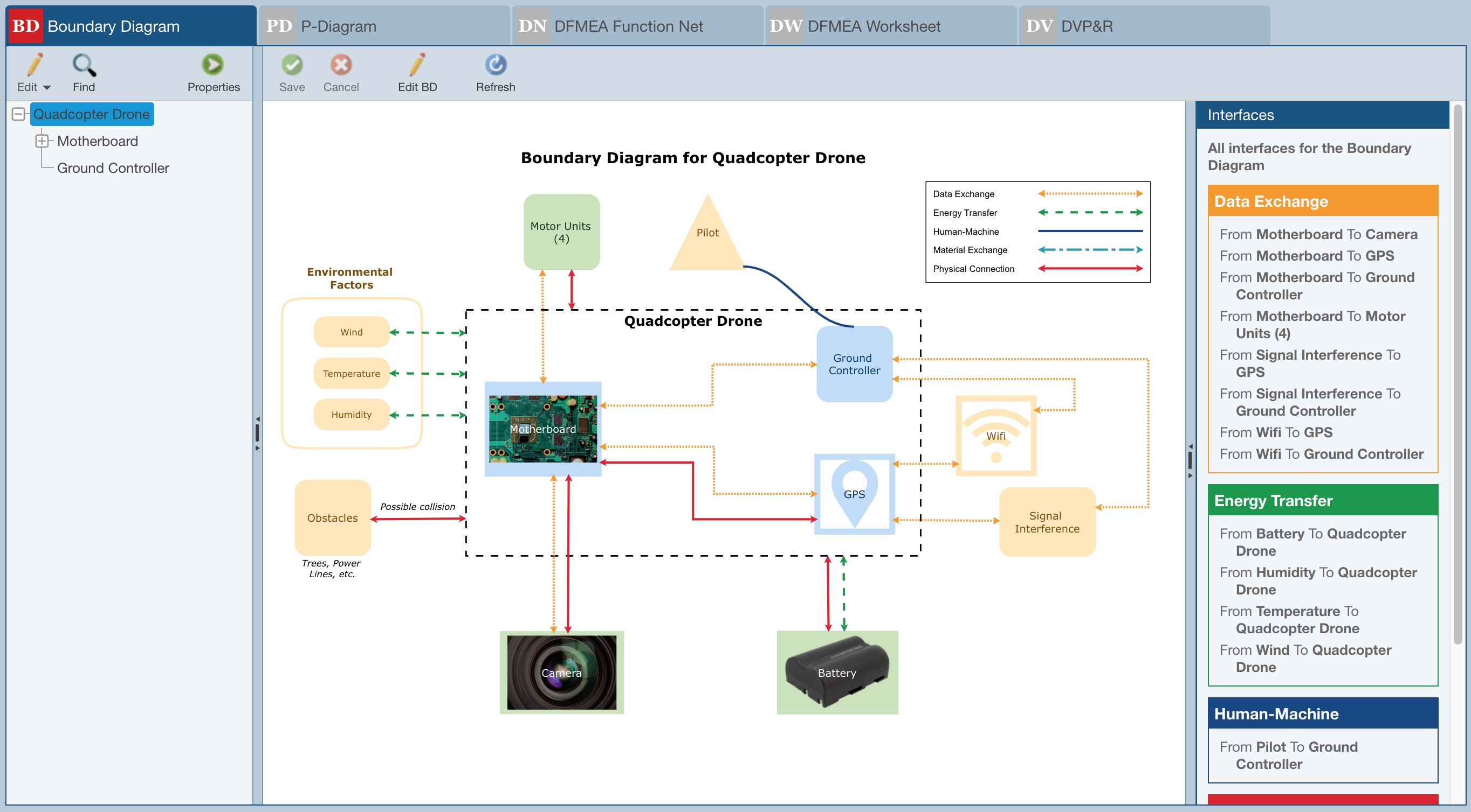
The example Boundary Diagram for the Quadcopter Drone in the Drone Example Analysis identifies the focal points for the DFMEA as the Motherboard, Ground Controller, and GPS, which are all within the boundary. It also highlights the key interfaces between the main subsystems of the Quadcopter Drone and other subsystems such as the Camera, Battery, and Motor Units, as well as external factors including Environmental Factors, Obstacles, Signal Interference, Wifi, and the pilot.
In order to define the scope of the DFMEA, a Boundary Diagram depicts the relationships between subsystems and parts as well as interfaces with neighboring systems or environments. By identifying such interfaces, you can facilitate the analysis of such system interfaces in the DFMEA. Boundary Diagrams can be constructed at any level of detail with the key purpose being to identify the major elements in the system of focus, how those elements interact with each other and outside systems. Developing a well-defined Boundary Diagram can provide useful input for the DFMEA, including Functions and Causes of failure.
Boundary Diagrams in Relyence DFMEA are comprised of various types of Blocks and Interfaces.
There are 6 default supplied types of Blocks that can be included in any Boundary Diagram. They include:
- Analysis Tree Subsystem - represent the major elements of the system in focus and are subsystems or components defined in the Analysis Tree.
- Boundary - generally a dashed line rectangle that defines the scope for the DFMEA within the boundary; blocks within the boundary are under control of the Analysis team.
- External Factor - represent external elements whose interactions with other diagram elements should be considered; examples include environmental effects such as wind, temperature and humidity, as well as customer usage.
- Legend - optional element that can be displayed to provide a key for all configured Interfaces.
- Other Subsystem - represents a subsystem that is not within the scope of the analysis but whose interactions with other diagram elements should be considered.
- Text - can be used to include titles or notes on any Boundary Diagram.
Note that default Relyence Block types cannot be deleted, but their properties can be customized as needed. See Help topic Configuring Boundary Diagram Interfaces and Blocks for more details.
There are 5 default supplied types of Interfaces that can be included in any Boundary Diagram. They include:
- Data Exchange - used to represent information exchange between blocks. Examples include: electrical signals, wiring harnesses, various computer inputs/outputs, and the interaction between a TV and remote control.
- Energy Transfer - used to represent the transfer of energy from one block to another. Examples include friction or motion transfer (such as with gears) and heat transfer, such as that between a CPU and a heat sink.
- Human-Machine - used to represent the interaction between a human and a device. Examples of systems that include Human-Machine interfaces are vehicles (gas and brake pedals), computers (keyboard and mouse), and many devices with manual switches.
- Material Exchange - used to represent the exchange of any type of material from one block to another. An example is the flow of gasoline from vehicle gas tank to combustion engine.
- Physical Connection - used to represent blocks that are physically connected such as blocks that are clamped, bolted, or welded together.
Note that default Relyence Interface types can be customized or deleted. Custom Interface types can also be added. See Help topic Configuring Boundary Diagram Interfaces and Blocks for more details.
Additionally, three very useful references where you can find details about Boundary Diagrams include:
- Ford FMEA Handbook Version 4.2
- AIAG & VDA FMEA Handbook
- SAE J1739
See also Help topic The Boundary Diagram Editor for more details on editing your Boundary Diagram(s).