Building your RBD
You build your RBD by adding blocks to your diagram and describing their associated data parameters.
From the toolbar, click the dropdown arrow next to Insert. The list allows you to select to insert a single block, redundant block, a subdiagram, a repeated block, a branch, a block from a library, or a subdiagram from a library. For example, to insert a new block directly after the currently selected block in your active diagram, select Insert>Block.
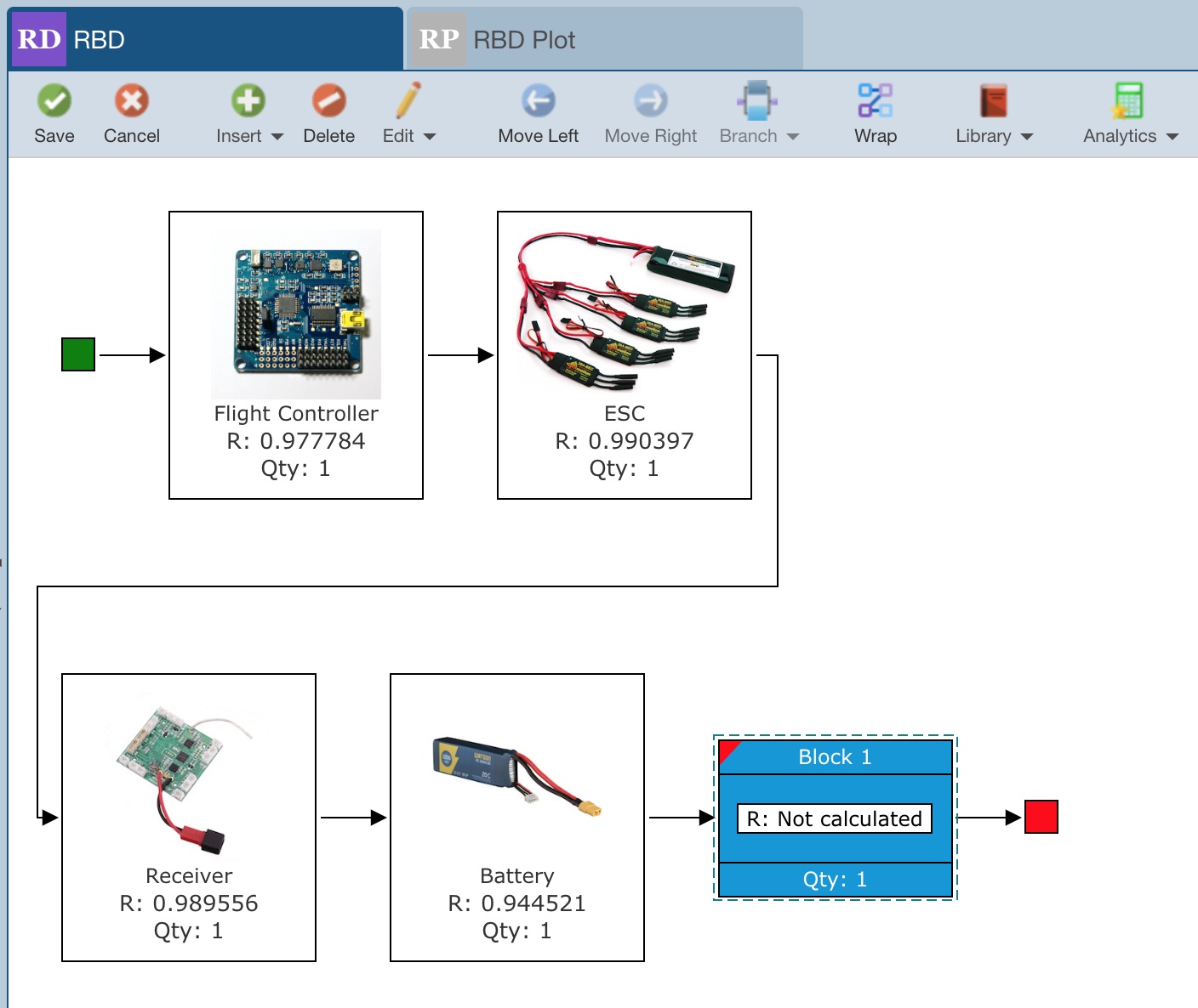
Once inserted, the new block is automatically selected for you.
RBD includes the ability to auto-wrap so you can control the layout of your diagram by clicking Wrap from the toolbar. Relyence RBD will automatically layout your diagram with the selected block below the current blocks and connected correctly.
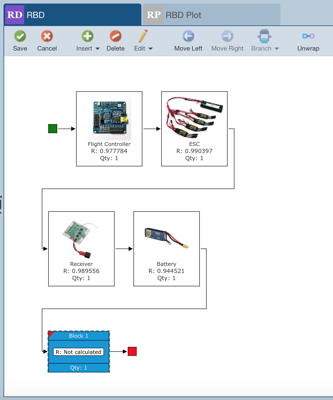
You can click Unwrap to move the block back to its original in-line location. The wrap feature of RBD allows you to effectively manage your RBD layout. The layout of your RBD on your display also controls how your RBD is printed.
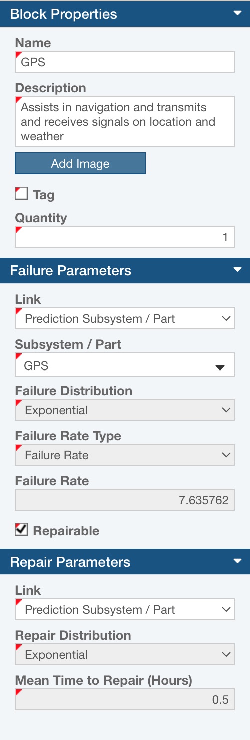
The next step is to enter the Properties for the blocks in your diagram. You can do so from within the Properties pane to the right of the RBD pane.
You can enter a Name and Description.
Note: If you plan to Link the Block to a Subdiagram, Prediction Subsystem / Part, or Weibull Life Data set - see notes below regarding Link and associated parameters - the Name and Description (Subsystems / Parts only) will be entered for you from the linked item.
- When a Block is linked to a Subdiagram, the Block Name will be populated with the Subdiagram Name.
- When a Block is linked to a Prediction Subsystem / Part, the Block Name will be populated with the Subsystem Name or Part Part Number and the Block Description will be populated with the Subsystem or Part Description.
- When a Block is linked to a Weibull Life Data Set, the Block Name will be populated with the Weibull Life Data Set Name.
Below the Description, the Add Image button allows you to add an image if you would like.
The Tag checkbox is a special indicator field you can use for any purpose you desire.
The following set of fields are used to define the characteristics of this block that will enable the calculation engine to model the block in order to evaluate overall RBD metrics.
Quantity: enter the number of units of this block that are present in your system
Redundancy Type: select the type of redundancy, if employed, for this block. When the quantity is set to 1, there can be no redundancy, so this selection is hidden. If you enter a quantity greater than 1, you can select from the list of Series, Parallel, Standby - Cold, Standby - Warm, and Standby - Hot redundancy types.
If a Redundancy Type other than Series is selected for a block, the following additional fields will appear:
- Quantity Required: If you select a non-series redundancy, the Quantity Required field will be shown for you to enter the quantity of units required for operation. For example, you may have 2 of the same units in a redundant configuration, but one is off and in standby mode and only turned on when the first unit fails. In this case, the Quantity would be 2, but the Quantity Required is 1.
- Switch Probability: If you select a non-series redundancy, the Switch Probability field will be shown for you to enter the likelihood the switchover to use a redundant component upon failure will be successful. You can enter a value from 0 - 1. A "0" indicates the switch will always fail, a "1" indicates the switch will never fail. The default is 1.
- Switch Delay (Minutes): If you select a Standby redundancy, the Switch Delay field will be shown for you to enter the switch delay time. The delay time is the number of minutes it will take to switch over to a backup unit upon failure in a standby redundant configuration. The default is 0.
- Set Standby Distribution: Applicable for Redundancy Type Standby - Warm only. Appears in the Failure Parameters section. When checked, allows you to set the Standby Distribution (Failure Distribution while in warm standby) and associated parameter.
Link and associated parameters: The Link function allows you to link the Failure Parameters for this block to another Subdiagram, or Prediction Subsystem or Part, or Weibull Life Data Set.
- If you choose to link to another subdiagram, you will need to select the Subdiagram you want to link to.
- If you choose to link to a prediction subsystem or part, you will need to select the Prediction Subsystem / Part from Reliability Prediction to link to.
- If you choose to link to a Weibull Life Data Set, you will need to select the Weibull Life Data Set to link to.
In any of these cases, the results for this block will obtain the characteristics for modeling from the underlying linkage and Name details can be auto-entered.
You will also notice that the RBD block changes to a green color from blue. Any blocks in your diagram that are linked in any way are shown in green to distinguish them from unlinked blocks.
Failure Distribution and associated parameters: If unlinked, you must enter the failure characteristics of the block. The failure parameters consist of the Failure Distribution and the corresponding distribution parameters. For more information about the failure distributions and the associated parameters, refer to the Failure and Repair Distributions topic. For blocks linked to items from a Reliability Prediction analysis or Weibull Life Data Set, these fields will be disabled because the data is retrieved from your prediction or weibull data.
Set Standby Distribution: When Set Standby Distribution is selected, the Standby Distribution and the corresponding distribution parameters appear. This is where you set the Failure data for the Blocks when in warm standby. For more information about the failure distributions and the associated parameters, refer to the Failure and Repair Distributions topic.
Repairable: If this component can be repaired, select the Repairable checkbox and define Repair Parameters.
Link and associated parameters: The Link function allows you to link the Repair Parameters for this block to Maintainability data, a Prediction Subsystem or Part, or a Weibull Life Data Set.
- The Link choice of Maintainability is only available if the Failure Parameters Link is set to Prediction Subsystem / Part. When selected, you can identify the Maintenance Level and the Mean Time to Repair (Hours) as calculated for that Maintenance in Relyence Maintainability Prediction for the repairable Subsystem / Part is used for the Mean Time to Repair (Hours) for the RBD Block.
- The Link choice of Prediction Subsystem / Part is only available if the Failure Parameters Link is set to Prediction Subsystem / Part. When selected, the value for Mean Time to Repair as set in the RBD Analysis Properties is used for the Mean Time to Repair (Hours) for the RBD Block.
- The Link choice of Weibull Life Data Set is always available if Weibull is included in the Analysis. When selected, you can select the Weibull Life Data Set that contains information relevant for the Mean Time to Repair, which will be displayed with the Repair Distribution and related parameters.
- The Link choice of None can also be selected when the Failure Parameters Link is set to Prediction Subsystem / Part, but you wish to enter the Repair Distribution and related parameters directly.
For more information on repair distributions and their associated parameters, refer to the Failure and Repair Distributions topic.
Note: If any Spare Pools exist in this Analysis, the Link to Spare Pool option will also appear in the Repair Parameters section. For more details, see Creating and Using Spare Pools.
Now you will need to save changes you made. Notice the red tag marks appear in the upper left corner of the newly entered block to indicate that unsaved data is present. Click Save in the toolbar. The newly entered block and its associated Properties are saved and you will notice the red tag mark no longer appear.
You can establish any Block as a Redundant Block by changing the Quantity to any value greater than 1. Once the Quantity is greater than 1, set the Redundancy Type, Quantity Required and Switch Probability, if applicable. Or, to insert a block with a default Quantity of 2 and a default Redundancy of Parallel, use Insert>Redundant Block.
Note that this topic described inserting and customizing a Block or Redundant Block. For details on other options from the Insert menu, see the following topics:
- Subdiagram - Managing your RBD Layout
- Repeat - Using Repeated Blocks
- Branch - Adding Branches to your RBD
- Repeat as Branch - Adding Branches to your RBD and Using Repeated Blocks
- Block from Library - the "Using a Block Library when performing Block Diagram Analysis" section of Block Libraries
- Subdiagram from Library - the "Using the RBD Library when performing RBD Analysis" section of RBD Libraries