Getting Started with Relyence RCM
If you would like to review a video overview of this Getting Started Guide, go to our online videos for Relyence RCM.
1. Sign in to Relyence
To begin, make sure you are signed in to Relyence. For details on signing in, see Signing in and Signing out.
You must have a Relyence account to sign in to Relyence. If you do not yet have a Relyence account, you can register for one for free.
You may possibly see the Announcements dialog when first signing into Relyence. The Announcements automatically scroll, or you can review them using the previous and next arrow keys. For any Announcements you do not wish to see again, select the Don't show me this again checkbox. Once you have reviewed all the Announcements, click the 'x' (Close) button in the upper right corner of the Announcements dialog.
2. Open the Example Analysis
First, let's make sure Relyence RCM is active.
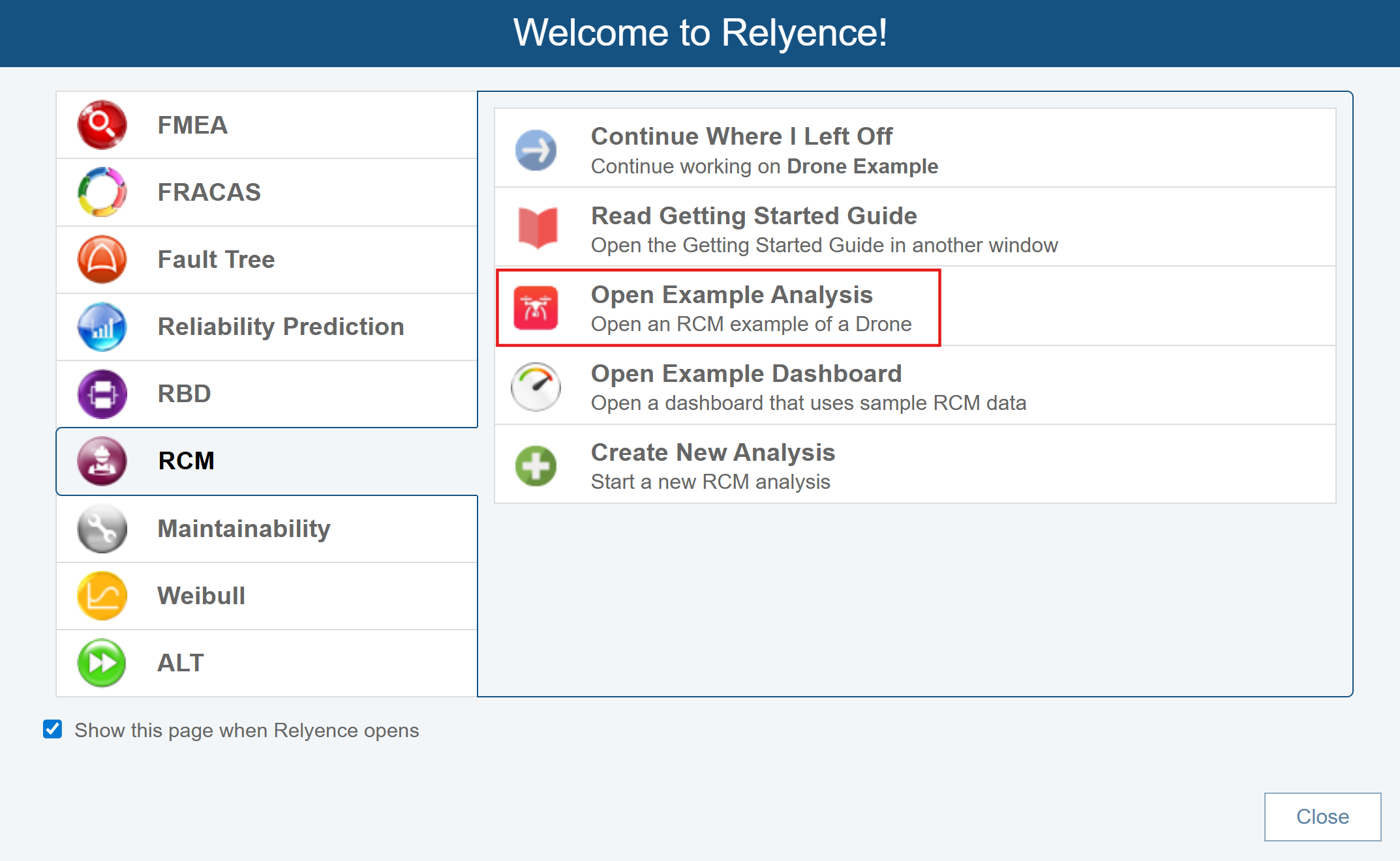
After you have signed in, you may see a Welcome dialog. If a Welcome dialog does not appear, click Welcome to Relyence from the Help dropdown menu in the upper right of the Relyence header bar.
If you were previously working on an Analysis, you will see the Continue Where I Left Off option at the top of this dialog, otherwise it will not appear. If you are using a Trial version, the Show this page when Relyence opens option will not appear. This option is only available using a licensed version of Relyence.
Click the RCM tab on the left to activate Relyence RCM. Then click Open Example Analysis.
For this tutorial, we will use the Drone Example Design RCM supplied with Relyence RCM. Our Drone Example references information from Relyence FMEA. This example is based on the DFMEA (Design FMEA) data from the Drone Example. Relyence RCM can be used with all other types of FMEAs including Process FMEA (PFMEA), Piece-Part FMECAs, and Monitoring and System Response FMEAs (FMEA-MSR); however, they will not be covered in this tutorial. For more information on FMEA types, please refer to the FMEA section of this guide. Please note that RCM can operate stand-alone. However, it is very common, and also commonly recommended, that RCM analyses start with FMEA for efficiency.
When you open an Example for the first time, you will see the Revert Example pop up appear. You are free to make changes and save your changes to the Example Analysis. If you want to revert to the original Example at any time, click Revert Example. You will get a message asking if you are sure before your changes are discarded. Click Got it! to dismiss the pop up.
For this tutorial, we assume an unmodified original Example is being used. If you are not sure if you are using an unmodified version of the Example, click Revert Example from the Sidebar. You will be asked if you want to lose your changes and reopen the Example in its original version. Click Yes.
If you continue with a modified version, just be aware that screen shots or other functions may not operate exactly as described in this tutorial.
When complete, your Drone Example with its data appears in the main window.

3. Review the Analysis Tree and RCM Data Tabs
There are two parts to the RCM window. The left pane is the Analysis Tree and the large right pane contains your RCM data tabs - your Decision Diagram and RCM Worksheet.
Analysis Tree and Analysis Diagram pane
The leftmost portion of the RCM window displays the Analysis Tree or Analysis Diagram. The Analysis Tree section allows you to create a hierarchical representation of the system or process you are analyzing. You can use the Analysis Tree to break down your system in any way you want for easier data management. You do not have to use the Analysis Tree if you prefer not to.
You can control the size of the Analysis Tree pane by using the leftmost splitter control. You can control the size of the Failure Mode Data pane by using the rightmost splitter control.

The left pointing arrow at the top of the splitter bar control collapses the Analysis Tree pane. To reopen the pane, click the right pointing arrow of the splitter bar control. To adjust the size of the pane, use the splitter control in the center. The right pointing arrow at the bottom will reopen the pane if it is collapsed or size it to full screen if the pane is visible.
Relyence RCM supports modeling your product or system visually using the Analysis Diagram. The Analysis Tree pane toggles between the Analysis Tree view and the Analysis Diagram view using the Edit>Show Diagram and Edit>Show Tree commands on the Analysis Tree pane toolbar. For an overview of using the Analysis Diagram, go to Getting Started with Relyence Analysis Diagram.
RCM Pane
The main RCM window has two tabs that include all the data related to the RCM process: the Decision Diagram and the RCM Worksheet.
Both the Decision Diagram and RCM Worksheet are customizable. The Drone Example uses some of the built-in RCM templates supplied with Relyence RCM. You can modify the supplied templates or create your own unique ones, see the Customizing the RCM Data Views section of this guide for more information.
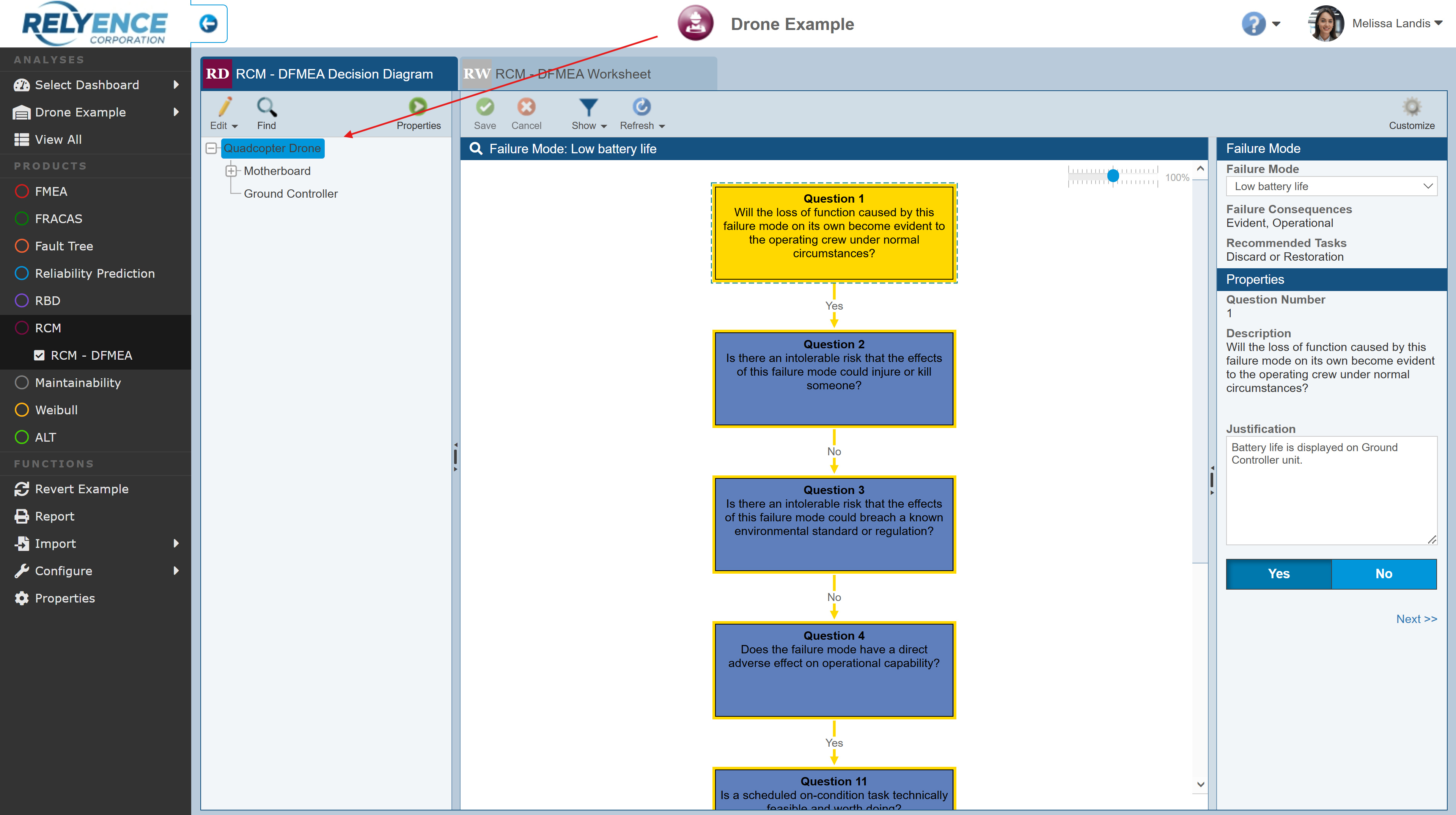
Click the Quadcopter Drone in the Analysis Tree pane to select it.
Decision Diagram
Click on the first tab to display the RCM - DFMEA Decision Diagram.

The Decision Diagram pane consists of the flowchart-like diagram on the left and the Failure Mode data pane on the right.
The Decision Diagram displays a series of questions that help you determine the best approach for your maintenance plan for the specific Failure Mode selected.
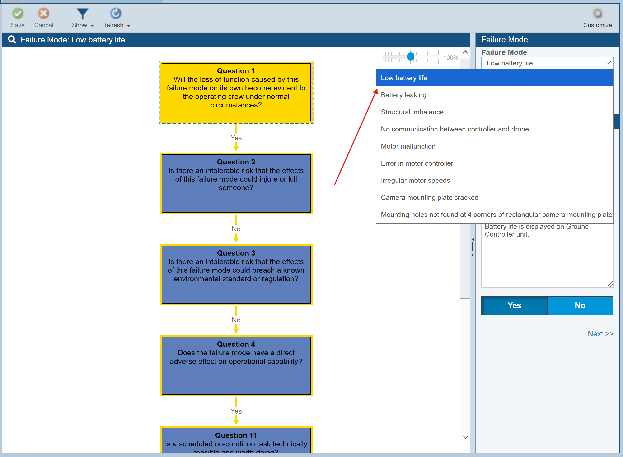
Click the Failure Mode dropdown list to view the list of Failure Modes associated with the Quadcopter Drone.
The Failure Modes identified in Relyence FMEA are shown. (Note: If you choose to use RCM in a stand-alone fashion and not integrated with Relyence FMEA, this list would show Failure Modes entered directly into Relyence RCM.)
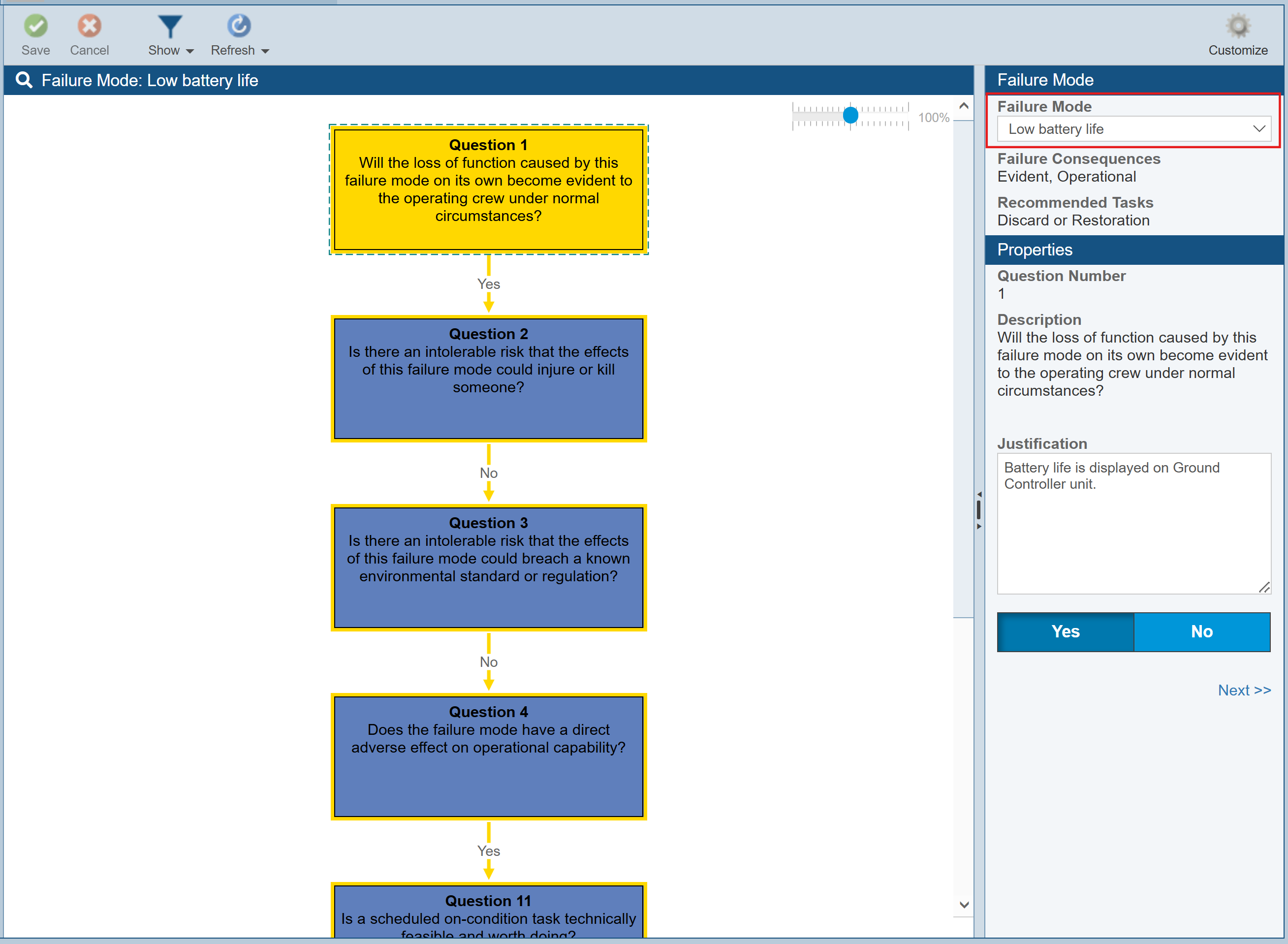
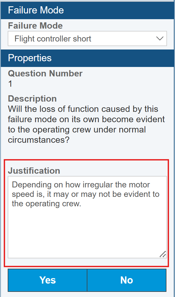
Make sure the Low battery life Failure Mode is selected in the list. The Failure Mode section displays the results of the Decision Diagram process: the Failure Consequences and Recommended Tasks. The lower section displays the Properties associated with the currently active Question in the Decision Diagram. The currently active Question is highlighted in yellow in the Decision Diagram.

You can see the Justification and the answer to the Question (Yes or No highlighted).

Click the Next>> button at the bottom of the Properties section to go to the next Question in the diagram.
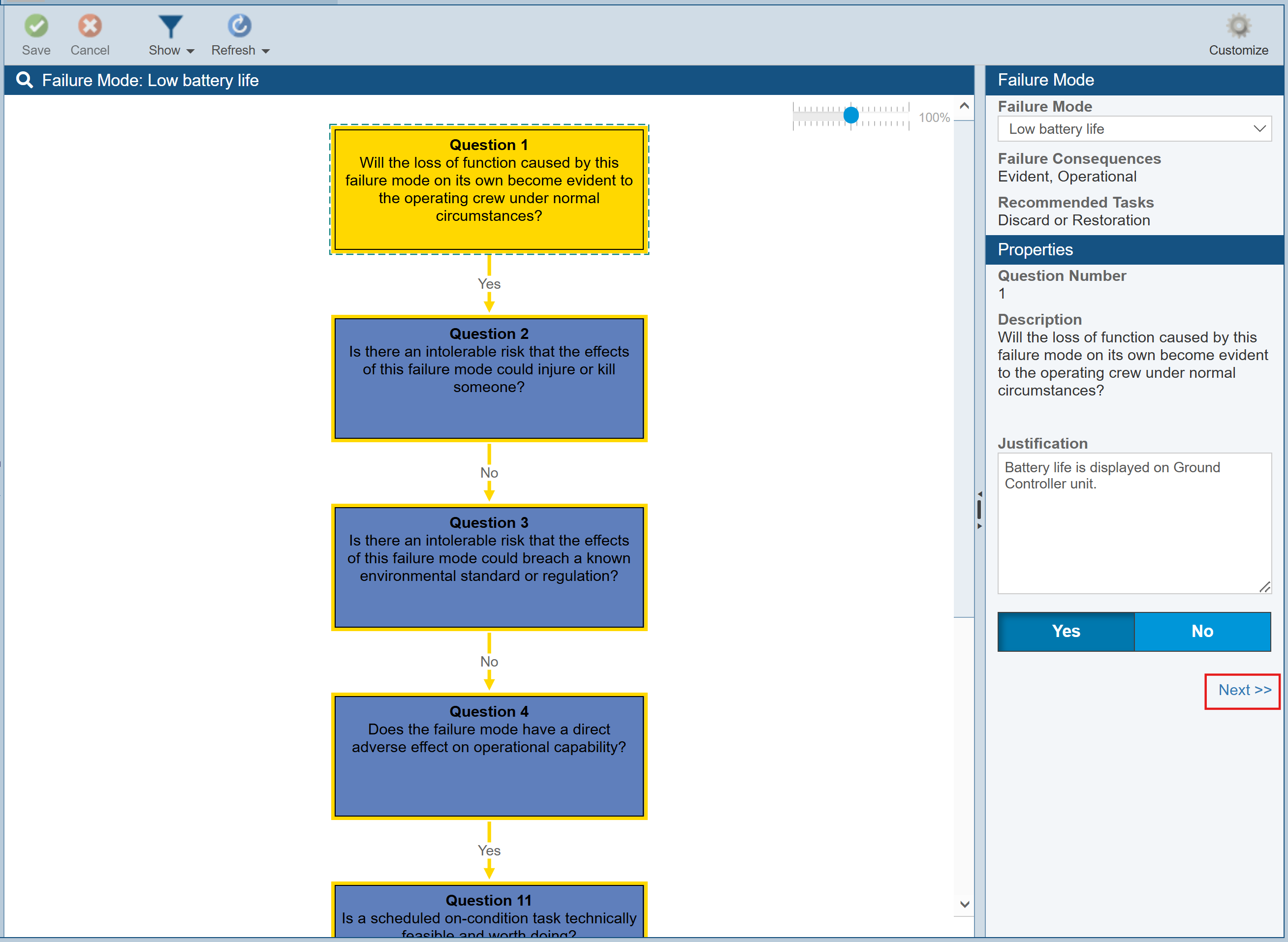
You can use the <<Previous and Next>> buttons to navigate through the Decision Diagram.
You can also choose to filter your Decision Diagram for viewing. There are three options for viewing the Decision Diagram. Click the Show icon in the RCM pane toolbar to see the selections of All, Possible Outcomes, or Selection Only.
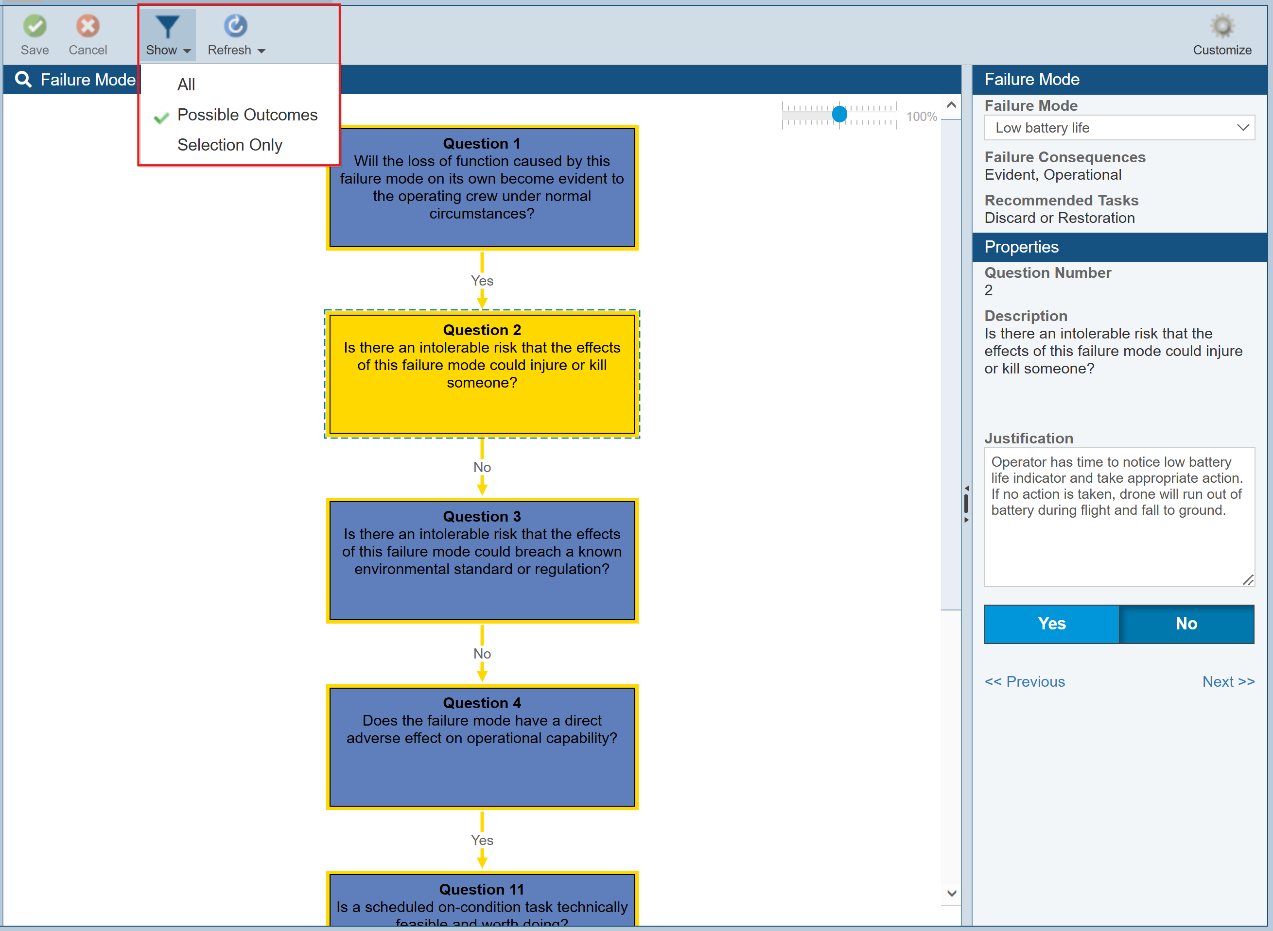
All will show all possible Questions and Answers. Possible Outcomes shows only the Answer path for answered Questions and both paths for unanswered Questions. Selection Only shows only the path of the Answer for answered Questions and nothing below unanswered Questions. You can click the options to see how the Decision Diagram is filtered based on the option selected.
Select Show>Selection Only for the Low battery life Failure Mode. Click Next>> and review the series of Questions and Answers and noted Justifications. Note that the end result is to periodically replace the battery to avoid a battery failure and mitigate the probability of a damaged drone.
RCM Worksheet
Click the RCM - DFMEA Worksheet tab to move to second tab of the RCM pane: the RCM Worksheet. The RCM Worksheet tab name indicates which FMEA your RCM is connected to. In this case we are working in conjunction with our DFMEA data, so the tab is labeled RCM - DFMEA Worksheet. In other cases, the tab may be labeled RCM - PFMEA Worksheet, RCM - FMEA-MSR Worksheet, or RCM - FMECA Worksheet.
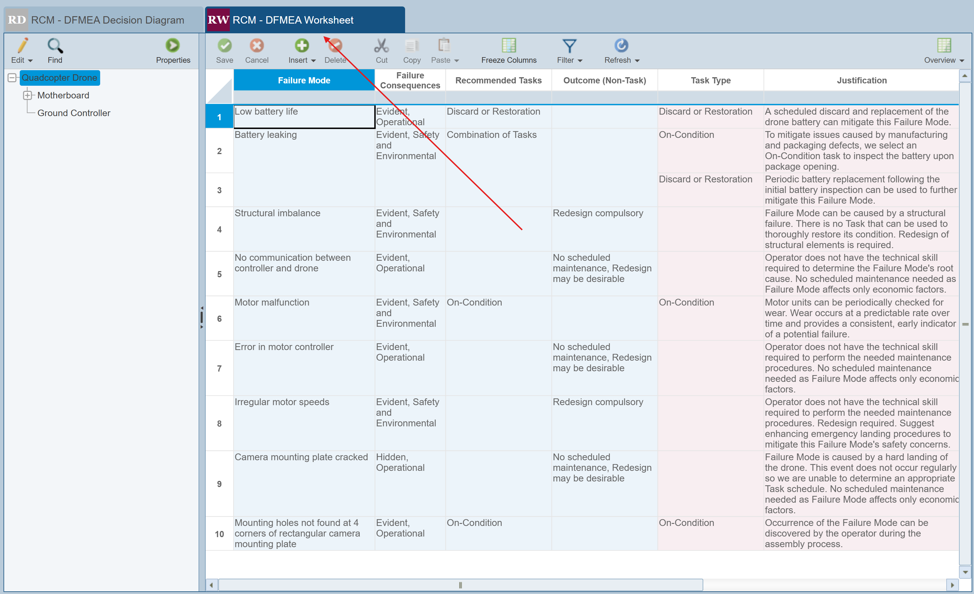
The RCM Worksheet is your main working area for performing your Reliability Centered Maintenance analyses. The RCM Worksheet is where you describe the Maintenance Tasks required to implement your maintenance plan.
The RCM Worksheet is color-coded to help when completing your analyses. The various data "groups" are color-coded to help visualize their relationships. Failure Mode related data appears in blue, Task related data appears in rose.
When you activate the RCM Worksheet, the Failure Mode you were working on in the Decision Diagram is automatically selected for you.
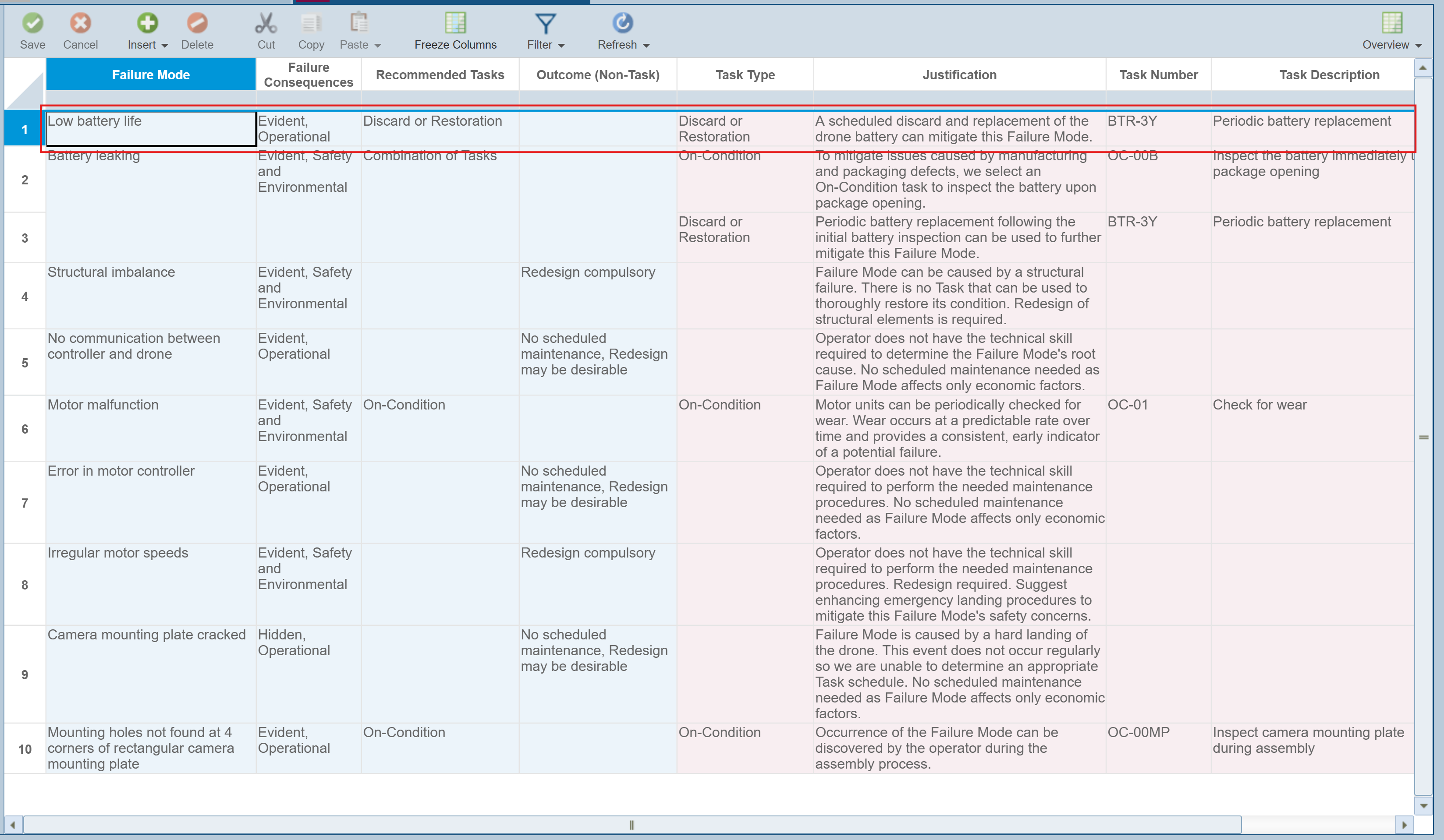
You can view the Task information entered for the Low battery life Failure Mode. You can see that the end result for the Low battery life Failure Mode is to periodically replace the battery to avoid a battery failure and mitigate the probability of a damaged drone.
4. Report
To generate a report of your RCM Worksheet, click Report from the Sidebar.
The Report Options dialog appears.
Enter "My RCM Report" for the Report Title.
Select Current RCM for the RCM to include on the report.
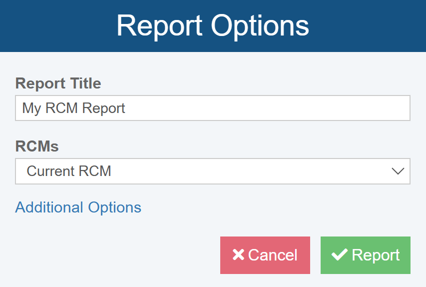
If needed, click Additional Options to see additional reporting options. For more details about these options, see Generating RCM Reports.
Click Report to generate the report.
The report appears in a new browser tab.
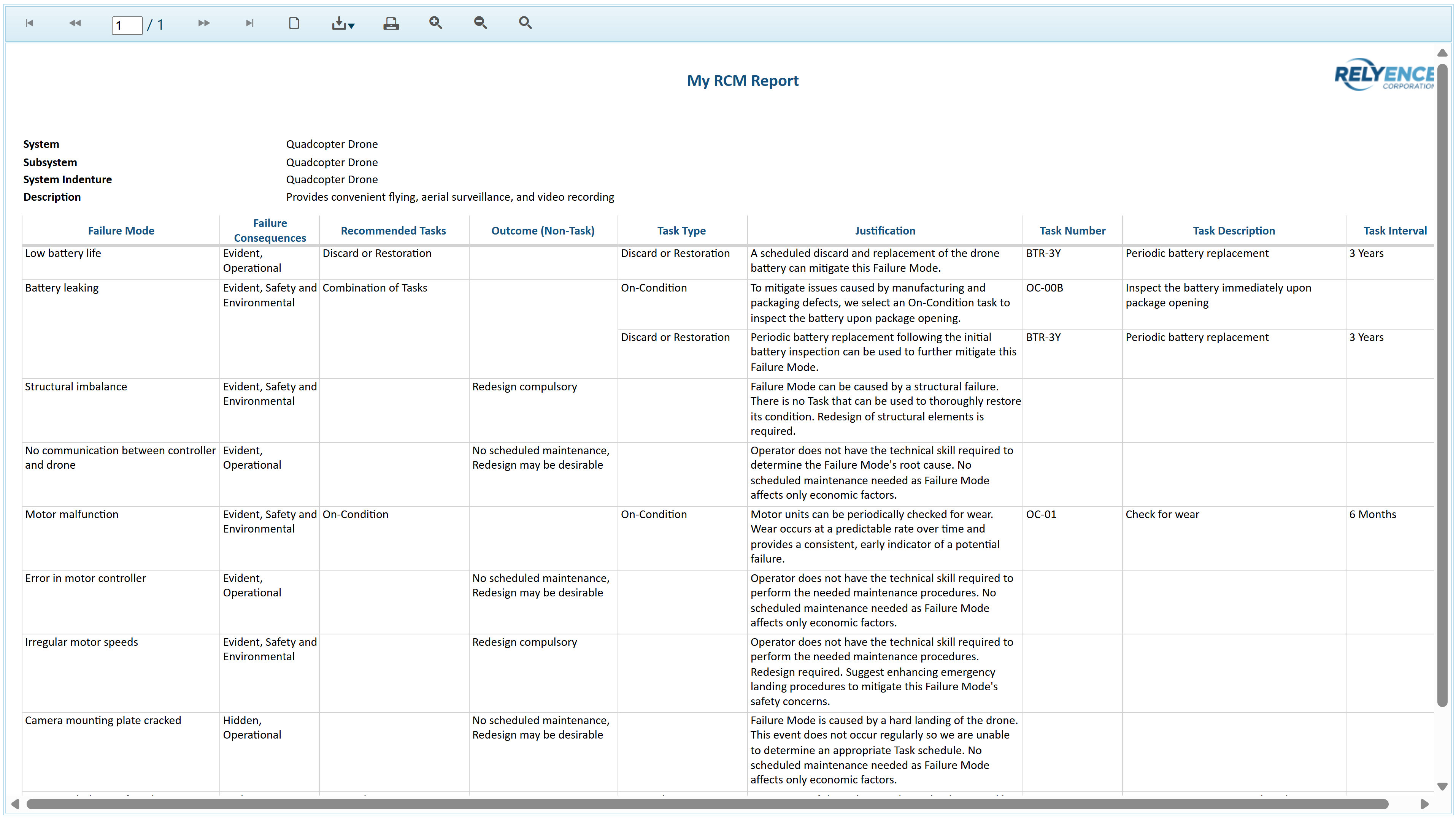
You can print the report, or save it in a PDF, Excel, PowerPoint, TIFF, or Word format.
Close the Report browser tab when you are done viewing the report.
You can also generate reports of the Decision Diagram by selecting Report from the Sidebar when the Decision Diagram tab is active. For more details, see the "Generating RCM Decision Diagram Reports" section of the Generating RCM Reports topic.
5. Adding RCM data
We are now going to add more analysis data into our RCM analysis.
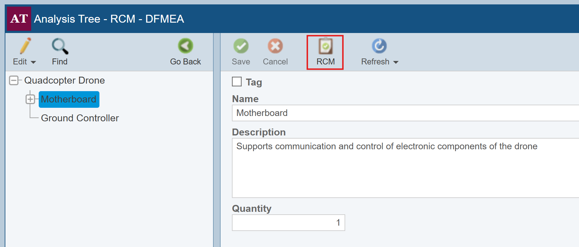
In our Drone Example, we have performed RCM analysis for several items of our Analysis Tree, but not the Motherboard. Now, we have made the decision to perform an RCM analysis on the Motherboard. To enable RCM analysis for the Motherboard, click Motherboard in the Analysis Tree pane to select it. Then click Properties in the Analysis Tree toolbar to view the Properties of the Motherboard.
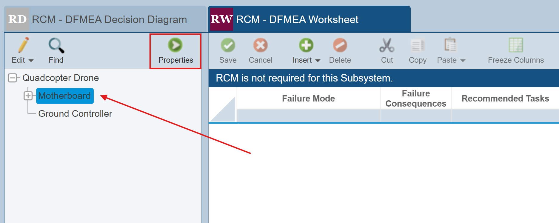
Click the RCM icon in the Properties pane toolbar.
The RCM selector dialog appears. Notice that the checkbox next to Motherboard is clear, indicating that RCM analysis is not required for this subassembly. Select the checkbox next to Motherboard to enable RCM analysis for the Motherboard.
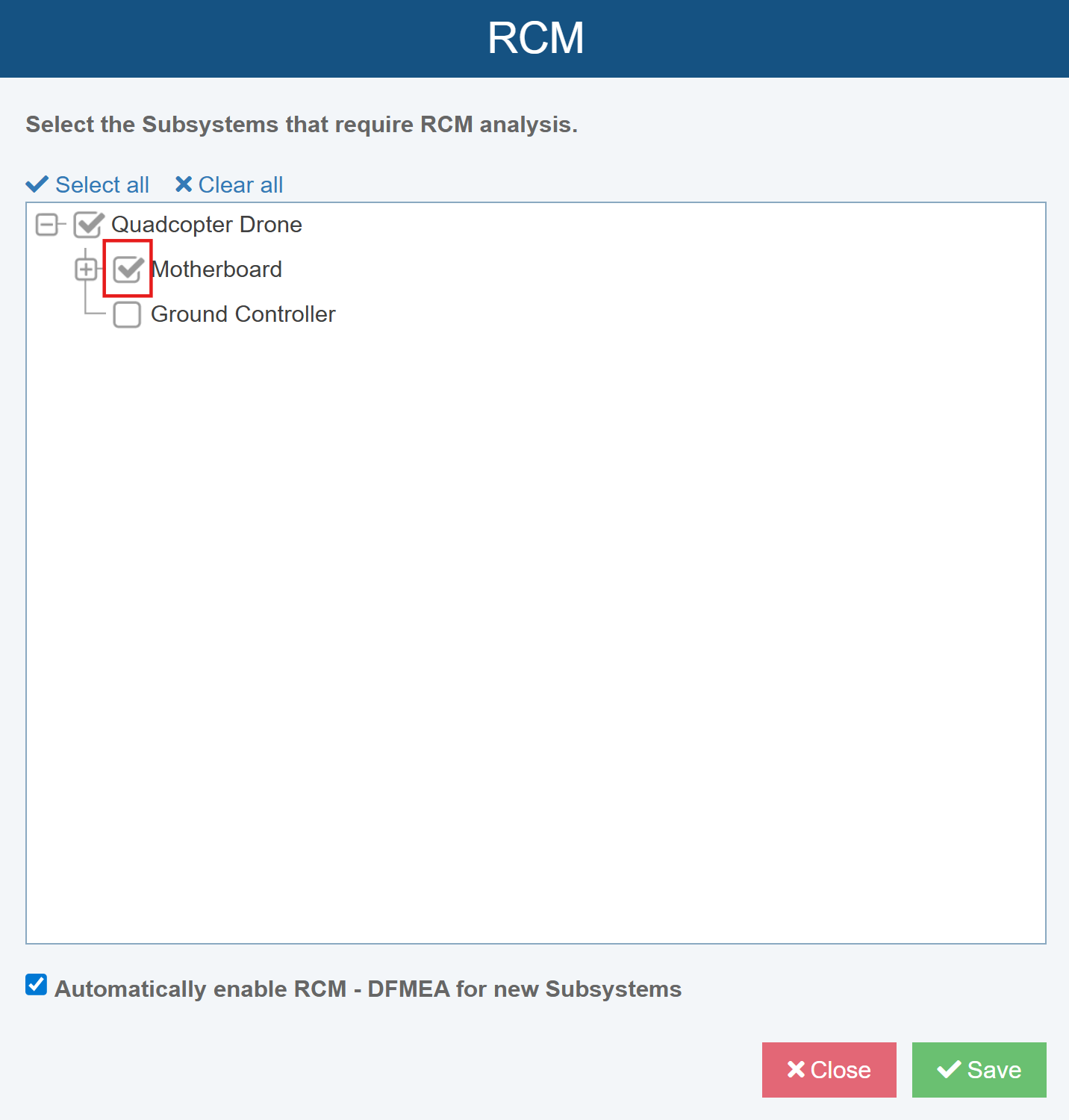
Click Save to save this change and then click Close to close the dialog. Click Go Back in the Analysis Tree toolbar to return to the RCM tabs.
Click the RCM - DFMEA Decision Diagram tab to select the Decision Diagram. Click the Failure Mode dropdown list to see the list of Failure Modes identified in the Drone Example FMEA for the Motherboard.
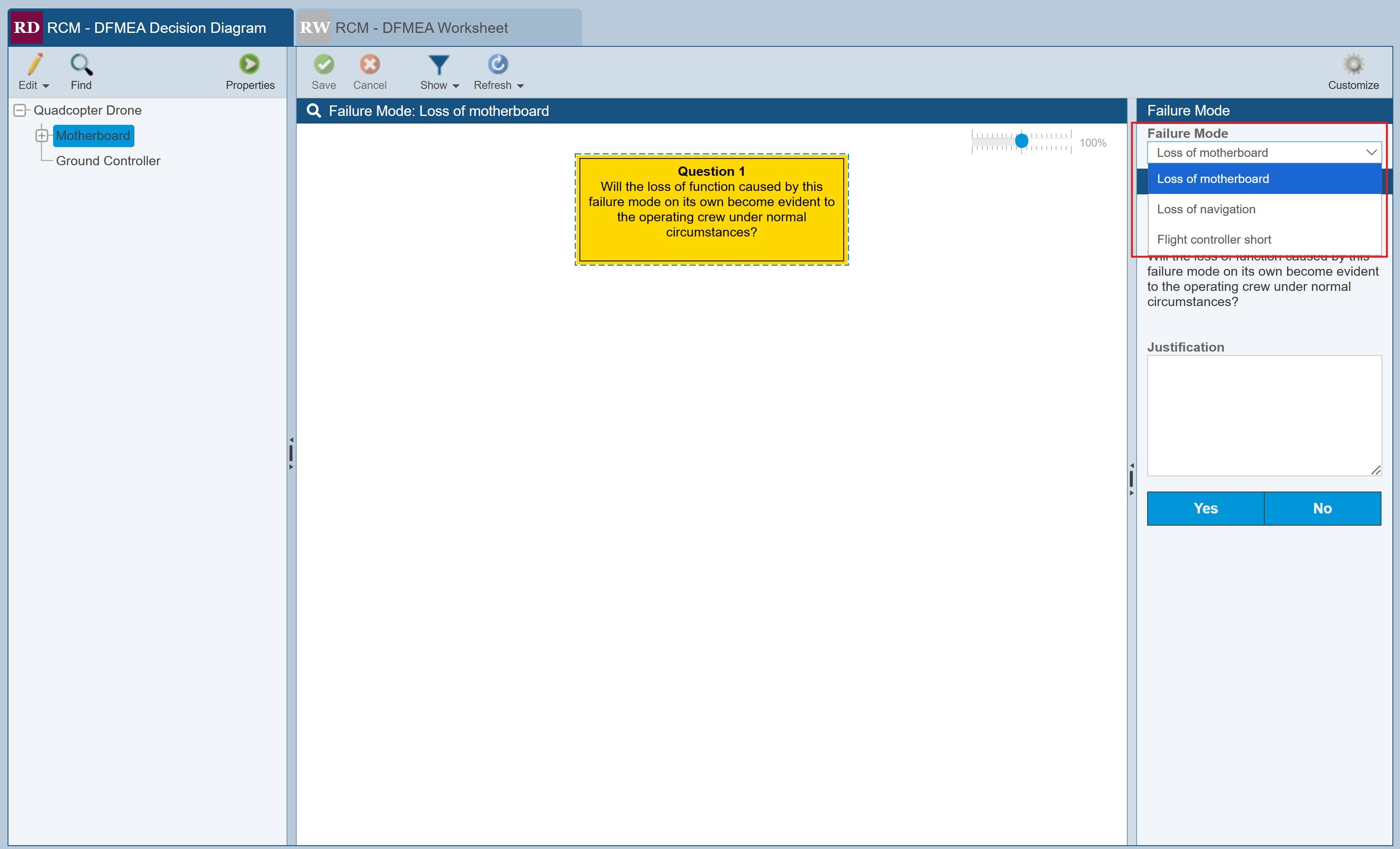
For this example, we will step through the RCM process for one of the 3 Failure Modes - the Flight controller short. To do so, first click the Show icon and select the Possible Outcomes option. Then, select Flight controller short from the Failure Mode dropdown list.
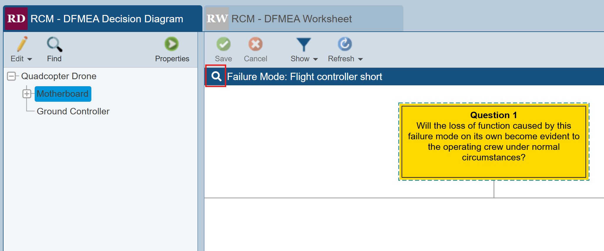
Let's see what information we have about this Failure Mode from our already completed FMEA. Click the FMEA Insight icon (with the magnifying glass) in the upper bar of the Decision Diagram. The FMEA Insight icon always displays the selected Failure Mode text, which is Flight controller short in this case.
The FMEA Insight dialog, which in this case is the DFMEA dialog because we are viewing details of our DFMEA, appears.
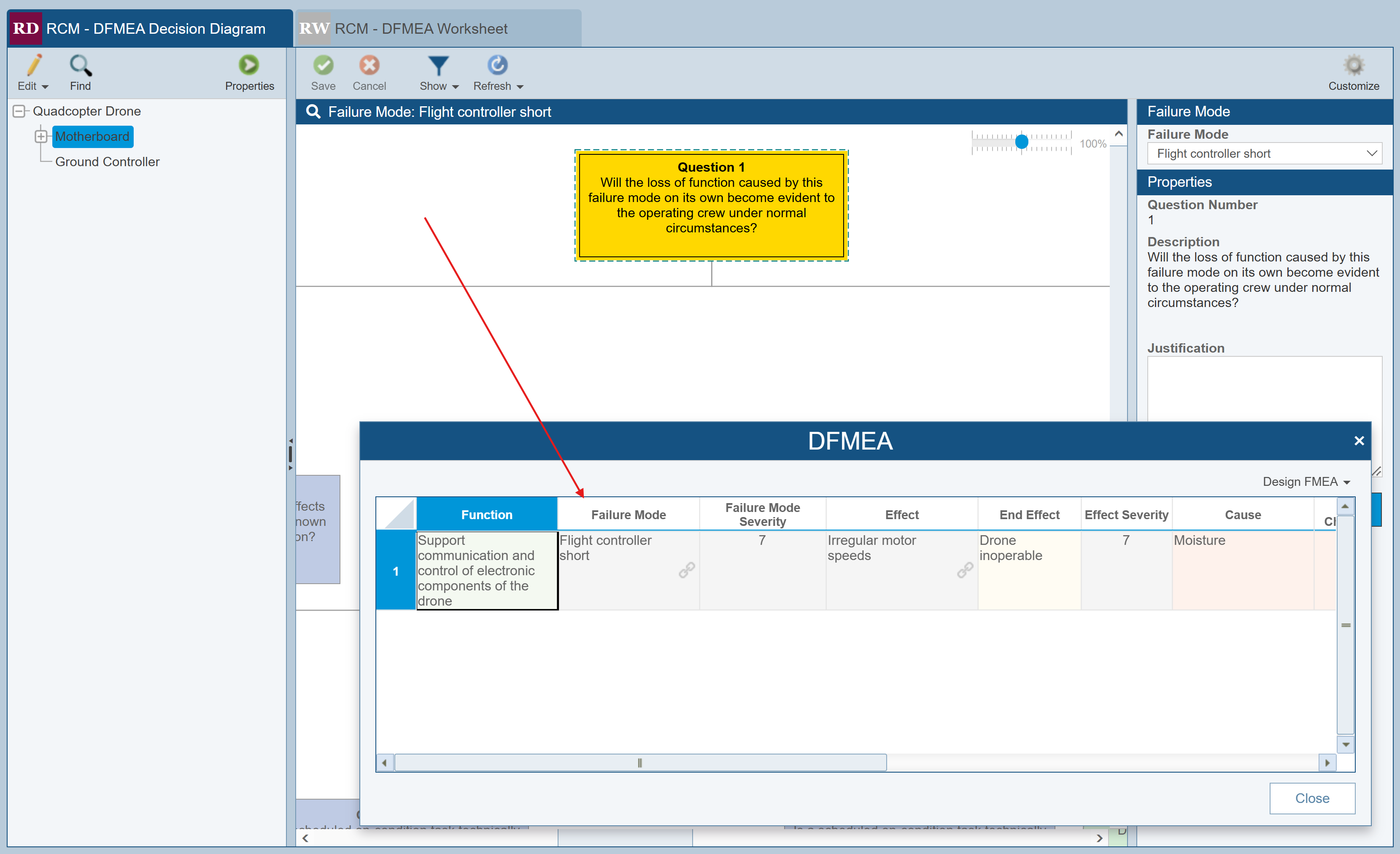
We can see that the Cause of this Failure Mode is moisture and the Effect results in irregular motor speeds. The Severity is 7, Occurrence is 5, and Detection is 5, resulting in an RPN (Risk Priority Number) of 175. This value remains in our acceptable (green) range; however, it is on the high side, so we'd like to implement some type of maintenance procedure to help mitigate this failure if possible.
Click Close to close the DFMEA dialog.
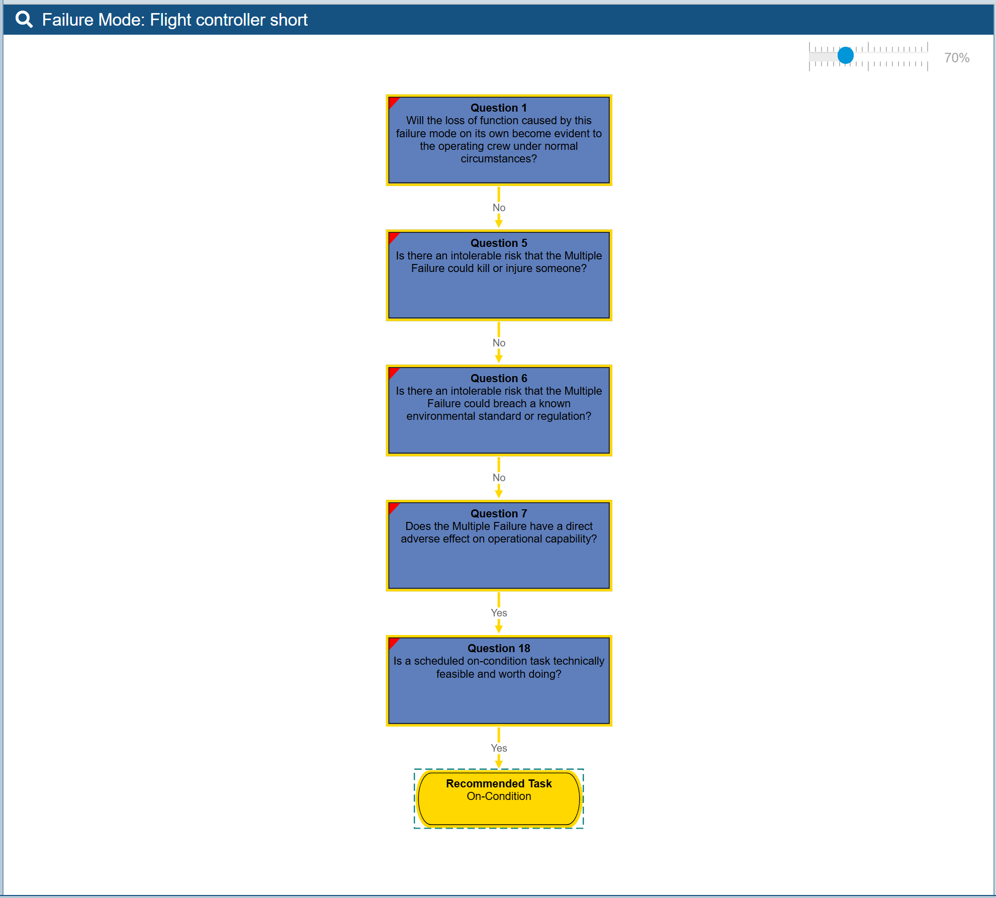
The first step is to proceed through the Questions in the Decision Diagram to evaluate the best options for maintenance to mitigate this Failure Mode.
Question 1 is "Will the loss of function caused by this failure mode on its own become evident to the operating crew under normal circumstances?" Enter the Justification: Depending on how irregular the motor speed is, it may or may not be evident to the operating crew.
Click the No button to move to the next Question. The next is Question 5: "Is there an intolerable risk that the Multiple Failure may kill or injure someone?" In this situation, because the failure is not apparent to the operator, this is considered a "hidden" failure. In many cases, hidden failures will have some type of protection added to the design in order to overcome the problem of the failure being not evident. In high risk situations, a catastrophic failure could occur if a hidden failure occurs at the same time the protection device fails. The case where a failure and its protection fails is considered a "Multiple Failure" - the terminology used in this Question. An example of a Multiple Failure would be if a smoke detector is in a failed state at the time a fire occurs. Based on the template we are using for this RCM analysis, the Questions use the "Multiple Failure" terminology. As noted, you can opt to modify the Decision Diagram if you prefer to use different Questions or change the Question text.
Enter the Justification: The risk is tolerable as the drone is still operable, but may be irregular.
Click the No button to move to the next Question. The next is Question 6: Is there an intolerable risk that the Multiple Failure could breach a known environmental standard or regulation? We don't need to enter a Justification for this question.
Click the No button to move to the next Question. The next is Question 7: Does the Multiple Failure have a direct adverse effect on operational capability? Enter the Justification: Can cause irregular motor speeds.
Click the Yes button to move to the next Question.
The next is Question 18: Is a scheduled on-condition task technically feasible and worth doing? Enter the Justification: Startup self-diagnostic test detects irregular flight controller speed and provides status to operator. Click the Yes button to move the end result of our Decision Diagram: an On-Condition Task.
Now that the Decision Diagram is complete, we will move to the RCM Worksheet to complete the information regarding the maintenance plan for the Flight controller short Failure Mode.
Click the RCM - DFMEA Worksheet tab to activate the RCM Worksheet. The Save Changes dialog appears asking us to save our Decision Diagram data. Click Save to save the information.
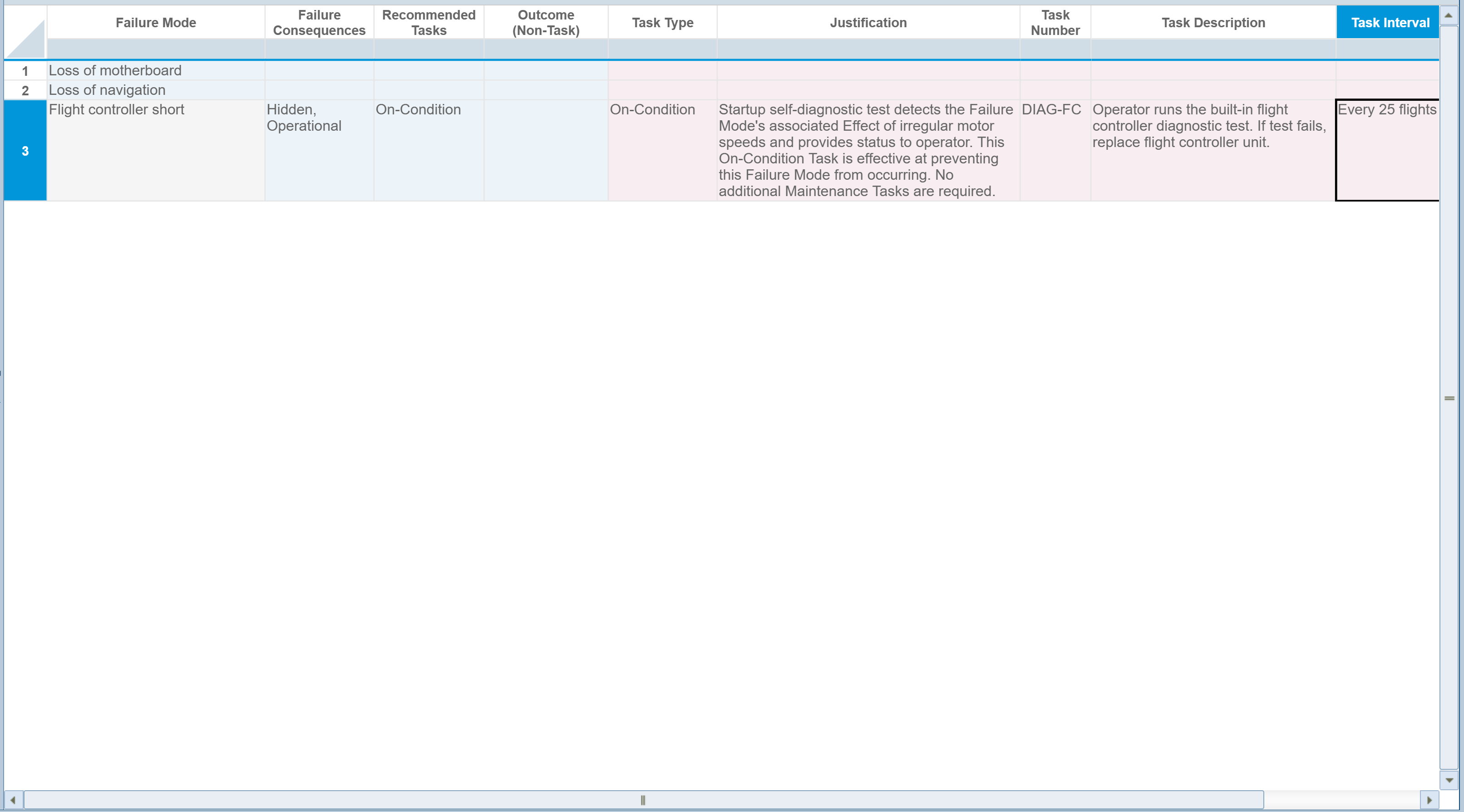
You can see the information gathered from the Decision Diagram entered into the Worksheet for the selected Flight controller short Failure Mode. The Recommended Tasks is set to On-Condition. Enter the following information for the Maintenance Task:
Task Type: On-Condition
Justification: Startup self-diagnostic test detects the Failure Mode's associated Effect of irregular motor speeds and provides status to operator. This On-Condition Task is effective at preventing this Failure Mode from occurring. No additional Maintenance Tasks are required.
Task Number: DIAG-FC
Task Description: Operator runs the built-in flight controller diagnostic test. If test fails, replace flight controller unit.
Task Interval: Every 25 flights
Click Save in the toolbar to save your changes.
6. Moving On
Congratulations! You have successfully completed the Relyence RCM Getting Started tutorial! You are ready to move on!
You are welcome to continue using the Drone Example to try out some other features and functions or start with a new Analysis. To create a new Analysis, click on Drone Example on the Sidebar menu, and then click Create New... on the submenu, or select Welcome to Relyence from the Help dropdown menu and click Create New Analysis. Remember that you can also click Revert Example to start over with an original Example.
Please note that there are limitations in the Trial version in the amount of data that can be entered. You will be notified when you have reached these limits.