• Products
    • Our Products
    • Relyence FMEA
    • Relyence FRACAS
    • Relyence Fault Tree
    • Relyence Reliability Prediction
    • Relyence RBD
    • Relyence RCM
    • Relyence Maintainability Prediction
    • Relyence Weibull
    • Relyence ALT
    • Relyence Studio
  • Industries
    • Industries Overview
    • Aerospace
    • Automotive
    • Commercial
    • Consumer Products
    • Defense
    • Healthcare
    • Manufacturing
    • Medical
    • Oil & Gas
    • Telecom
  • Services
    • Our Services
    • Training
    • Implementation
    • Technical Support
    • Resources
  • Blog
  • About Us
    • Our Team
    • Join Us
    • Why Relyence
    • Contact Us
  • Support

Call us today! 724.832.1900

wecare@relyence.com
My Account
RelyenceRelyence
  • Products
    • Our Products
    • Relyence FMEA
    • Relyence FRACAS
    • Relyence Fault Tree
    • Relyence Reliability Prediction
    • Relyence RBD
    • Relyence RCM
    • Relyence Maintainability Prediction
    • Relyence Weibull
    • Relyence ALT
    • Relyence Studio
  • Industries
    • Industries Overview
    • Aerospace
    • Automotive
    • Commercial
    • Consumer Products
    • Defense
    • Healthcare
    • Manufacturing
    • Medical
    • Oil & Gas
    • Telecom
  • Services
    • Our Services
    • Training
    • Implementation
    • Technical Support
    • Resources
  • Blog
  • About Us
    • Our Team
    • Join Us
    • Why Relyence
    • Contact Us
  • Support

Mathematical Foundations for Reliability Block Diagram

Home » Mathematical Foundations for Reliability Block Diagram
Mathematical Foundations for RBD

Mathematical Foundations for Reliability Block Diagram

April 15, 2026 RBD, Reliability Block Diagram

This article is an excerpt from our “Mathematical Foundations for Reliability Block Diagrams” white paper.

Reliability Block Diagram (RBD) Analysis

One of the most useful tools in modeling a system’s reliability is the Reliability Block Diagram (RBD). It provides a way to graphically represent a system as a network of its base components and offers numerous calculations that demonstrate how these components contribute to overall system behavior. RBDs are highly versatile, applicable to simple cases, like series or parallel circuits, as well as more complex scenarios such as those involving repairable components or standby configurations.

To fully realize the benefits of using RBD for system analysis, it is helpful to understand the mathematical principles behind this powerful tool. This white paper investigates the mathematical processes that underpin RBD analysis. Topics include analyzing non-repairable and repairable systems, Monte Carlo simulation, important RBD metrics, standby redundancy, and more.

RBD Analysis for Repairable Systems

A system is repairable if at least one of its components is repairable. In addition to having a failure distribution, a repairable component also has a repair distribution. Once the component has failed, the repair distribution takes effect and influences the repair time. After the repair, the component again undergoes the failure distribution. In some scenarios, a component can carry over some prior wear after being repaired, causing it to resume partway through the failure distribution. For the purposes of this white paper, we assume that repairs are perfect. This means that components are restored to being as good as new, so the failure distribution takes effect as if it were starting from time t = 0 .

The behavior of switching back and forth between failure and repair distributions causes analytical calculations to become extremely difficult, if not impossible. The complexity also increases significantly with the number of repairable components. Fortunately, Monte Carlo simulation is a tool that works exceptionally well in these scenarios.

Monte Carlo Simulation

In the context of RBD analysis, the Monte Carlo method involves generating times from components’ distributions to simulate a possible run of the system. This process is repeated over many iterations, and then all the results are averaged to provide an estimate of the true results. As the number of iterations increases, the estimates will converge to the actual results due to the law of large numbers.

Random Time Generation

To better understand how this method works, it is important to know how a random time is generated from a probability distribution. This is done through a statistical process known as inverse transform sampling. First, we generate a random value uniformly distributed between 0 and 1, which is something a computer can do using a pseudorandom number generator. We interpret this number as the reliability of the distribution and work backwards in the reliability equation to solve for time. This time is our desired random value from the distribution. Note that a specific simulation can be reproduced using a random seed.

As an example, consider a Weibull distribution with shape parameter β = 1.5 and scale parameter η = 100. The reliability of this distribution is given by R(t) = e–(t/η)β . Rearranging this formula to solve for time gives t = η(-ln(R))(1/β) . Suppose our random number generated between 0 to 1 is 0.6, which we assign to the reliability. Solving for time, we have t = (100)(-ln(0.6))(1/1.5) ≈ 63.9021. This is the randomly generated time to fail or time to repair.

How a Single Iteration Works

Now we can demonstrate how a single iteration is completed for a repairable component. Assuming that the component is initially working, we first generate a random value from its failure distribution and use it as the failure time. Once the component has failed, we then draw a time to repair from the repair distribution and add it to the failure time to get the point in time when the component is repaired. After the repair, we add on the next generated time to fail, and the process continues as far in time as desired.

This gives us the time ranges when the component is working and when it is failed. Doing this for each component allows us to determine the periods of time when the system is in a failed state. Below is an example of how system states are derived from the component states.

Example Monte Carlo Simulation

Consider the following simple diagram. Suppose that we simulated an iteration up to 100 hours with these component state changes: Block  fails at 30 hours and is repaired at 60 hours, block  fails at 50 hours and is repaired at 80 hours, and block  fails at 70 hours and is repaired at 90 hours.
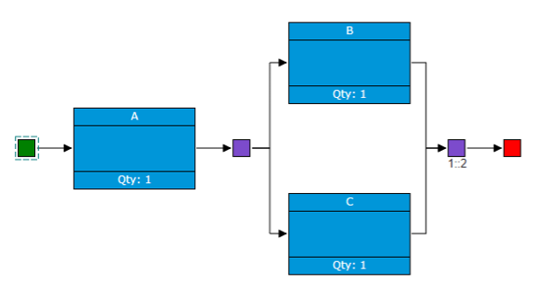
RBD Diagram

Path Sets

First, it can be helpful to look at all of the path sets of the diagram, which are all of the ways the system can succeed. In this case, a successful path can be traced from start to end through components A and B or though A and C, so at least one of these combinations must be working for the system to be active. In other words, the system is in a working state when the active component combinations are A and B, A and C, or A, B, and C. Next, we go through each component state change and see how they affect the overall system in the table below.

Time in Hours Active Components System State
30  B and C Failed
50 C Failed
60 A and C Working
70 A Failed
80 A and B Working
90 A, B, and C Working

This table shows the system fails at 30 hours, is repaired at 60 hours, fails at 70 hours, and is repaired at 80 hours. This information calculated over many iterations is all that is necessary to arrive at the key metrics for repairable systems.

Learn More

The “Mathematical Foundations for Reliability Block Diagrams” white paper covers the following extensive list topics:

  1. Non-repairable Systems
    1. Non-repairable System Metrics
      1. Reliability
      2. Failure Rate
    2. Computing System Metrics
      1. Series Configuration
      2. Parallel Configuration
      3. k-out-of-n Configuration
    3. Non-repairable System Example
  2. Repairable Systems
    1. Monte Carlo Simulation
      1. Random Time Generation
      2. How a Single Iteration Works
      3. Example Monte Carlo Simulation
    2. Repairable System Metrics
      1. Availability
      2. Hazard Rate
      3. Reliability and Failure Rate
    3. Confidence Bounds
      1. Confidence Level
      2. Computing Availability with Confidence Bounds
      3. Example Repairable System Availability Calculation
  3. Additional RBD Concepts
    1. Steady State Results
      1. MTTF
      2. Steady State Availability
      3. MTTR and MTBF
    2. Standby Redundancy
      1. Switching Mechanism
      2. Hot Standby
      3. Cold Standby
      4. Warm Standby
      5. Standby Configuration Calculations
      6. Effects of Standby Components on System Availability

Download the full white paper here. To learn more about Relyence RBD, feel free to contact us or schedule a personalized demonstration webinar. Or you are welcome to give us a free trial run today!

Tags: Availabilitycold standbyconfidence boundsConfidence Levelhazard ratehot standbyk-out-of-nMonte Carlo simulationMTBFMTTFMTTRnon-repairable systemsparallelrepairable systemsseriessteady state availabilityswitching mechanismsystem modelingWarm Standby
Share

You also might be interested in

2023 R1 Header

Welcome to Relyence 2023 Release 1!

Feb 10, 2023

Watch Release Highlights Video The beginning of 2023 comes with[...]

How are Failure Rates Calculated in Reliability Prediction Analysis?

How are Failure Rates Calculated in Reliability Prediction Analysis?

Jul 3, 2023

Reliability Prediction analysis is one of the primary techniques used[...]

Maintainability Prediction: A Comprehensive Overview

Maintainability Prediction: A Comprehensive Overview

Mar 14, 2023

Maintainability is an important aspect in system continuous improvement efforts.[...]

Search

Recent Posts

  • Mathematical Foundations for Reliability Block Diagram
  • Welcome to Relyence 2026
  • The Relyence API: A Practical Developers Guide
  • Introduction to the Relyence API
  • Reliability Prediction Analysis with IEC 61709

Categories

  • 217Plus
  • ALT
  • ANSI/VITA 51.1
  • CAPA
  • China's GJB/z 299
  • Dashboard
  • Fault Tree
  • FMEA
  • FRACAS
  • Fundamentals
  • General
  • How-to
  • IEC 61709
  • Knowledge Bank
  • Life Data Analysis
  • Maintainability Prediction
  • MIL-HDBK-217
  • MTBF
  • News
  • NPRD/EPRD
  • NSWC Mechanical
  • Quality
  • RBD
  • RCM
  • Reliability
  • Reliability Block Diagram
  • Reliability Centered Maintenance
  • Reliability Growth
  • reliability growth analysis
  • Reliability Prediction
  • Reliability Studio
  • RGA
  • SN 29500
  • Telcordia
  • Weibull

Tags

8D AIAG AIAG & VDA ALT always-in-sync AP Availability China's GJB/z 299 cold standby Control Plan COPQ CP dashboard DFMEA EPRD failure mode fault tree fmea FMECA fracas FTA IEC 61709 ISO-9001 Knowledge Bank Maintainability MIL-HDBK-217 MIL-STD-1629 MTBF MTTF MTTR NPRD PFMEA Process Flow Diagram QMS RBD Redundancy Reliability Reliability Block Diagram reliability prediction RPN standby Telcordia Weibull What-If? Workflow

Connect with us

Start your free trial today! Try for Free!
Relyence Corporation logo

Driven by innovation. Focused on the future. Always improving.

AIAG Member Logo

Image Disclaimer: Some of the images featured on this website may have been generated or enhanced using artificial intelligence (AI) tools. These images are intended for illustrative purposes only and may not depict real people, places, or events.

FIND US HERE

  • Relyence Corporation
  • 540 Pellis Road, Greensburg, PA 15601
  • 724.832.1900
  • wecare@relyence.com
  • https://relyence.com

Privacy Policy

Terms of Service

Sitemap

FRESH FROM OUR BLOG

  • Mathematical Foundations for Reliability Block Diagram
  • Welcome to Relyence 2026
  • The Relyence API: A Practical Developers Guide

© 2026 Relyence Corporation All Rights Reserved. Relyence® is a registered trademark of Relyence Corporation.

  • Try for Free!
Prev
Relyence
Manage Consent

To provide the best experiences, we use technologies like cookies to store and/or access device information. Consenting to these technologies will allow us to process data such as browsing behavior or unique IDs on this site. Not consenting or withdrawing consent may adversely affect certain features and functions.

Functional Always active
The technical storage or access is strictly necessary for the legitimate purpose of enabling the use of a specific service explicitly requested by the subscriber or user, or for the sole purpose of carrying out the transmission of a communication over an electronic communications network.
Preferences
The technical storage or access is necessary for the legitimate purpose of storing preferences that are not requested by the subscriber or user.
Statistics
The technical storage or access that is used exclusively for statistical purposes. The technical storage or access that is used exclusively for anonymous statistical purposes. Without a subpoena, voluntary compliance on the part of your Internet Service Provider, or additional records from a third party, information stored or retrieved for this purpose alone cannot usually be used to identify you.
Marketing
The technical storage or access is required to create user profiles to send advertising, or to track the user on a website or across several websites for similar marketing purposes.
  • Manage options
  • Manage services
  • Manage {vendor_count} vendors
  • Read more about these purposes
View preferences
  • {title}
  • {title}
  • {title}