

FMEA, or Failure Mode and Effects Analysis, is an organized, systematic approach for assessing potential system or process failures and the resulting consequences, or effects, of those failures. The objective of an FMEA is to evaluate the risk associated with the identified failure effects and come up with a plan to detect, prevent, or mitigate those deemed most critical.
What is Process FMEA?
Process FMEA, or PFMEA, is a specific type of FMEA. The essential distinction between FMEA and PFMEA is that the term PFMEA denotes that a process is being analyzed. In contrast, DFMEA, or Design FMEA is another type of FMEA that denotes a design is being analyzed.
Once a product moves from the design stage into production, PFMEA becomes vital to ensure that product quality is maintained during the manufacturing process. PFMEA can be used on any process, not just in product manufacturing. For example, you could employ a PFMEA to analyze a process that is used when an emergency occurs. PFMEAs are broadly used throughout many industries and organizations to ensure processes are well controlled.
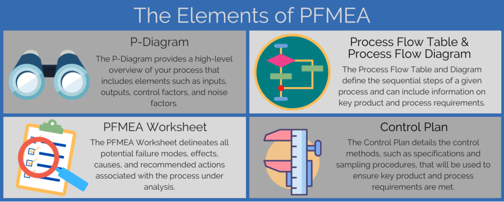
Elements of PFMEA
The core aspect of PFMEA involves identifying the potential failure modes of the process steps, the resulting effects and underlying causes of those failures, and then determining and implementing recommended actions to mitigate failures that are high risk. This data is captured in the central component of all PFMEAs – the PFMEA Worksheet.
Optionally, the PFMEA process can also include:
- P-Diagram, or Parameter Diagram
- PFT or PFD, or Process Flow Table or Process Flow Diagram
- PCP or CP, or Process Control Plan or simply Control Plan
Typically, the elements of the PFMEA are implemented in the following order:
- Create a P-Diagram
- Define the Process Flow
- Create the PFMEA Worksheet
- Complete the Control Plan
P-Diagram
The P-Diagram offers a high-level overview that aids in completion of the FMEA for the process under review. The P-Diagram can ultimately provide key inputs to the PFMEA as it focuses on inputs, outputs, control factors, and noise factors.
Process Flow Table or Process Flow Diagram
While the Process Flow, or the steps of the process in a sequential fashion, can be defined directly on the PFMEA Worksheet, it can also be specified and maintained on the Process Flow Table or Process Flow Diagram. The table-based format is known as the PFT, or Process Flow Table. The diagram format is known as the PFD, or Process Flow Diagram. Along with all steps of the process under review, the Process Flow Table or Diagram can also include key PFMEA Product Characteristics and key PFMEA Process Characteristics. Product Characteristics are features of the product that must be controlled; whereas Process Characteristics are features or elements of the process that affect or control the Product Characteristic in question.
PFMEA Worksheet
Completing the PFMEA Worksheet is the key element of all Process Failure Mode and Effects Analyses and, therefore, is included in all PFMEAs. The PFMEA Worksheet delineates all potential failure modes, effects, causes, and recommended actions associated with the process under analysis. Using the PFMEA Worksheet, you focus on identifying all potential failure modes for each Process Step. Reviewing the PFMEA Product Characteristics from the PFT or PFD can help to identify failure modes. Once failure modes are specified, you can define effects, causes, and other data relevant to your analysis.
Control Plan
Often as a final step in the PFMEA process, a Control Plan is created. The Control Plan details the methods you will use to control the PFMEA Product and Process Characteristics to ensure they meet requirements. The controls may define details such as specification, evaluation technique, and sample size and frequency. Control Plans provide clear documentation of the controls used to handle the potential failure modes that were identified in the PFMEA Worksheet. For this reason, Control Plans are very useful in the creation of operator instructions.
How to Control Your PFMEA Data with Relyence FMEA Software
As you can see, the data across the elements of the PFMEA process is interrelated. The better organized and integrated the PFMEA elements are, the more efficient and accurate your PFMEA will be. It is just one of the many reasons using software specifically designed for FMEA is the best way to perform failure mode and effects analyses. Relyence FMEA was designed specifically to optimize the PFMEA process so that your analyses are not only better controlled and organized but are also easier for you to complete and maintain.
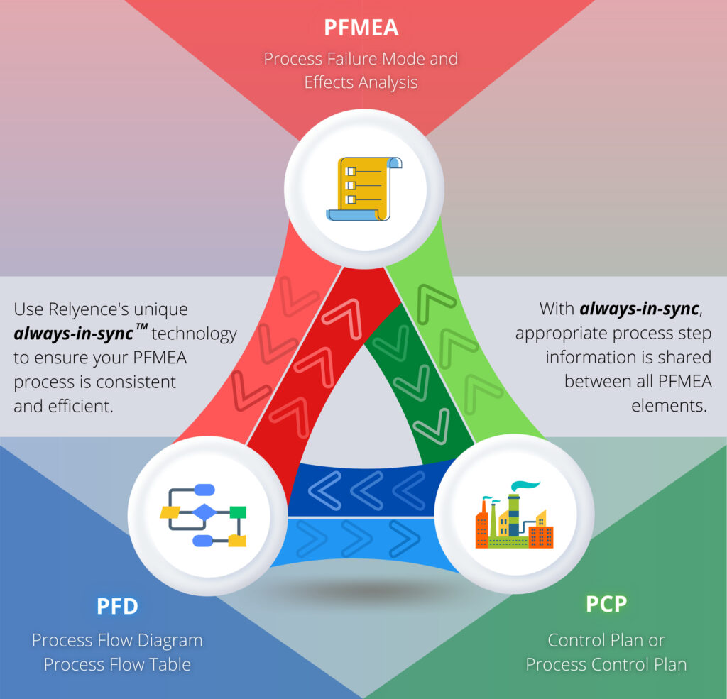
To support efficient and consistent PFMEAs, Relyence FMEA offers the unique and innovative always-in-sync technology. This Relyence-only capability takes PFMEA organization and control to a new level.
Always-in-sync Technology for Data Consistency and Control
Relyence FMEA software’s unique always-in-syncTM technology ensures that your PFMEAs remain organized and complete. All parts of your process: P-Diagram, Process Flow Table or Diagram, PFMEA Worksheet, and Control Plan are integrated for ease of use and efficiency. Additionally, the always-in-sync technology ensures that all elements of your failure analysis are accounted for.
Relyence PFMEA’s always-in-sync functionality is key to keeping your Process Steps organized as well as enabling you to easily share PFMEA Product Characteristic and PFMEA Process Characteristic data between the Process Flow Table and Control Plan.
Syncing Process Steps Across PFMEA Elements
In Relyence PFMEA you can enter or modify the Process Steps on the PFT, on the PFMEA Worksheet, and on the Control Plan. No matter where this data is entered or modified, the updates are automatically reflected across all other elements. This ensures that the Process Steps and related data are always up-to-date and consistent in all three places. Thus, you can build your process flow by defining the steps of your process on the Process Flow Table, PFMEA Worksheet, or Control Plan.
At the outset of your PFMEA, the Process Steps are often defined on the Process Flow Table as shown in the following video. Once the Process Steps are defined in one location, such as the Process Flow Table, note how they’re automatically available in the other two locations – the PFMEA Worksheet and Control Plan.
As you continue the PFMEA process, you may require changes or additions to your Process Steps. This may occur for a variety of reasons.
Example 1: Synced PFMEA Process Steps Across your PFMEA Elements
For example, as you are defining data on your PFMEA Worksheet, you may realize that a clarification may be required for one or more of your Process Steps.
Using our sample case from the video, as you define Failure Modes for the “Return clamps to storage” Process Step, you may realize that it would be ideal to have defined the storage location. Just as you can add a new Process Step in any of the three main worksheets and have it applied in all locations, you can also modify a Process Step in one location and have that change automatically reflected in all key PFMEA elements as shown in the following video.
Example 2: Synced PFMEA Process Steps Across your PFMEA Elements
For another example, as the PFMEA work progresses, you may also identify a new Process Step that should be included.
Using our sample case again, your team determines an additional step should be added after the inspection in order to “Correct camera installation on drone body”. On the PFT, PFMEA Worksheet, or Control Plan, select Insert>Process Step to add the new step. No matter where you choose to add it, the change is reflected across the PFMEA as shown in the following video.
Syncing Product and Process Characteristics
Relyence FMEA’s always-in-sync functionality also applies to PFMEA Product and Process Characteristics. PFMEA Product Characteristics are features of the product that must be controlled; whereas PFMEA Process Characteristics are features or elements of the process that affect or control the PFMEA Product Characteristic in question.
PFMEA Product Characteristics and PFMEA Process Characteristics may be entered on the PFT (or PFD) or on the Control Plan. Changes made to the Product Characteristics or Process Characteristics on the PFT or PFD are automatically reflected on the Control Plan and vice versa.
Example: Synced Product and Process Characteristics
For example, for the “Correct camera installation on drone body” Process Step, PFMEA Product Characteristics and PFMEA Process Characteristics can be added or modified on the PFT (or PFD) or Control Plan and will be automatically kept in sync across the two PFMEA elements as shown in the following video.
Conclusion
Relyence FMEA was designed and built to ensure the FMEA process is as smooth and efficient as possible for PFMEA. You can take advantage of Relyence PFMEA’s always-in-sync functionality to ensure consistency and efficiency while performing PFMEA with Relyence FMEA.
In addition to providing a comprehensive and well-managed framework for PFMEA, Relyence FMEA also supports DFMEA (Design FMEA), FMEA-MSR (Monitoring and System Response FMEA) as defined in the AIAG-VDA FMEA handbook, and FMECA (Failure Mode, Effects and Criticality Analysis).
If you are interested in learning more about Relyence FMEA sign up today for your own no-hassle free trial. Or, feel free to contact us to discuss your needs or schedule a personal demo.