

Reliability Predictions are one of the most widely used techniques in reliability analysis. The core function of a Reliability Prediction is to evaluate an electro-mechanical system to estimate or predict its failure rate. The methods used to assess failure rate are described in Reliability Prediction standards which consist of equations used to estimate the failure rate of the various electronic and electromechanical devices found in systems. Reliability Prediction standards have a long history in the reliability engineering field.
Reliability Prediction standards are developed based on the statistical analysis of a wide range of component data gathered in the field over a long time period. This data is then analyzed to develop a series of equations that can be used to model the underlying failure characteristics of devices. The equations include several variables that affect reliability, such as operating environments, temperatures, quality levels, and stress factors. There are a number of Reliability Prediction standards in use today, including MIL-HDBK-217, Telcordia SR-332 (formerly Bellcore), SN 29500, 217Plus, NSWC Mechanical, and ANSI/VITA 51.1.
In this article we will review how to perform a Reliability Prediction using IEC 61709, the “Electric components – Reliability – Reference conditions for failure rates and stress models for conversion” published by the International Electrotechnical Commission (IEC), which uses a modified approach to reliability prediction analysis.
How to Perform a Reliability Prediction Analysis
To perform a Reliability Prediction analysis, you describe all the underlying components in your system and their important characteristics. The Reliability Prediction engine then performs the necessary calculations to determine the overall failure rate and MTBF (Mean Time Between Failure) of your system.
The first step begins by listing all the components in your system design. You then compute the estimated failure rates of your components using the equations from the standard you choose to use. The predicted failure rate of the entire system is a compilation of the underlying component failure rates. In the simplest case, the system failure rate is the sum of the component failure rates. There are other methods to determine overall failure rate depending on additional data you may have; our in-depth guide explains other available techniques.
How is IEC 61709 Different from Other Reliability Prediction Standards?
As evidenced in its title, “Electric components – Reliability – Reference conditions for failure rates and stress models for conversion,” IEC 61709 provides a method for converting failure rates from one set of conditions to another. That is, it takes failure rate values obtained at reference conditions and provides a methodology to convert them to the given operating conditions.
The reference conditions are the most common set of environmental and operating conditions for the system. Failure rates established at the reference conditions are referred to as the base failure rates. For components not operating at the reference conditions, you can enter the actual operating conditions and the IEC 61709 standard then provides the equations needed to adjust the base failure rate to the failure rate at the operating conditions. Because they are adjusted to reflect actual operating conditions, converted failure rates help better predict true product lifetime.
Component base failure rates are sourced based on the methodology of your choosing. For example, you can choose to use failure rates obtained from actual use, from manufacturer data, or obtained from other prediction standards. When using IEC 61709 to perform Reliability Predictions, you must consider how to determine base failure rates and also gather data on the actual environmental and operating conditions of the components and system under evaluation.
How to Perform Reliability Prediction Analysis with the IEC 61709 Reliability Prediction Standard
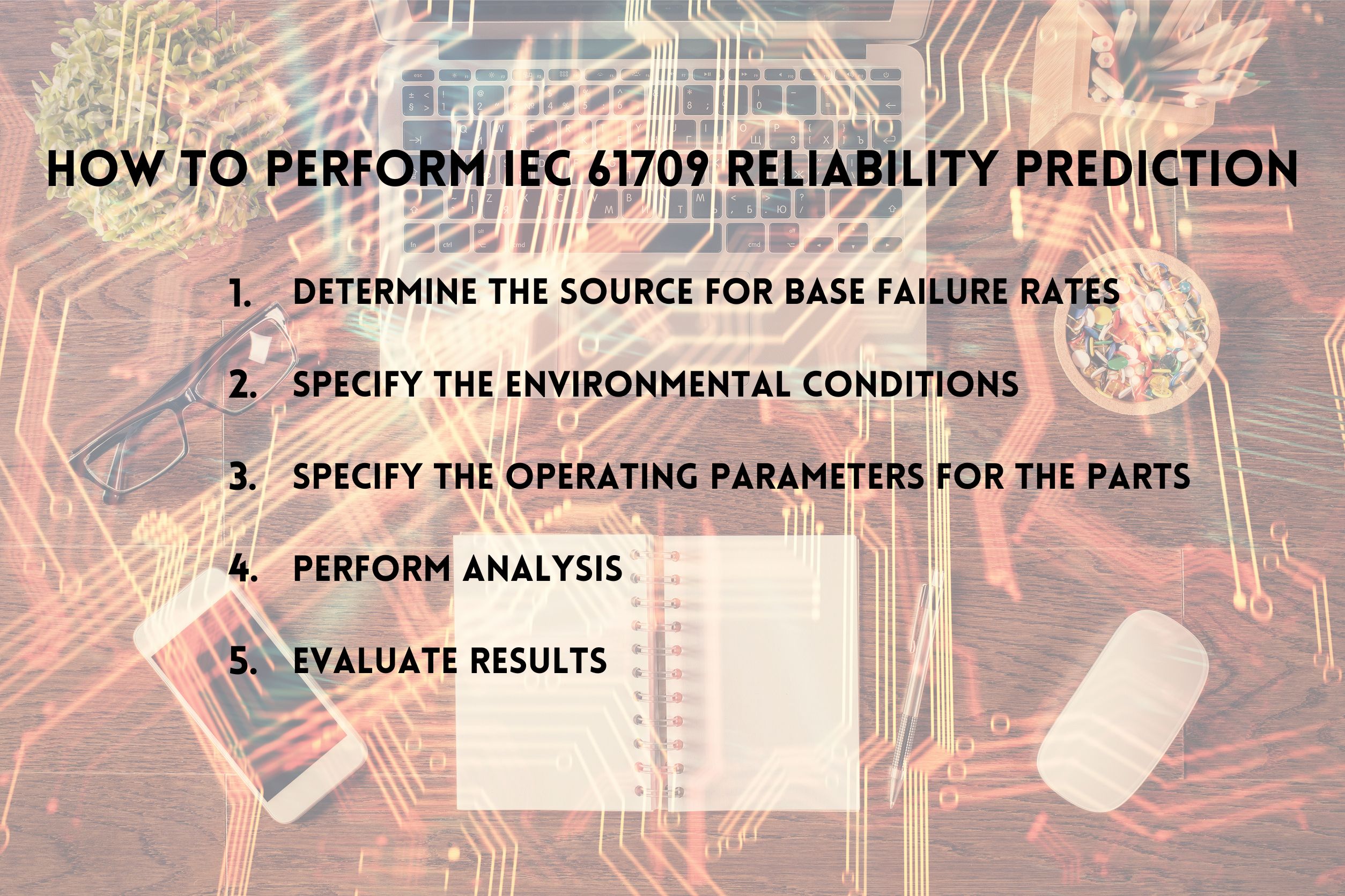
Step #1: Determine the Source for Base Failure Rates
As stated in IEC 61709, “This document requires failure rates in order to be useful.” Therefore, the first step is to determine how you will obtain base failure rate data. IEC 61709 suggests that the most useful source is actual field usage data. The second most useful is test data, which is often obtained from manufacturers’ data. Lastly, IEC 61709 recommends obtaining base failure rates from another reliability prediction standard. It can be difficult to obtain actual field-based failure rates or failure rates based on test data, so it is not uncommon for other prediction standards to be used as a source for base failure rates.
Step #2: Specify the Environmental Conditions
For IEC 61709, the base failure rates are established at the reference environment. If the overall system is operating at a different environment, then the operating environment must be specified in order to convert failure rates accordingly. Using IEC 61709, you specify both the Reference Environmental Application Factor (the environment used for obtaining the base failure rates) and the Operating Environmental Application Factor (the actual operating environment).
Step #3: Specify the Operating Parameters for the Parts
For the components of the system not operating at the reference conditions, the operating parameters must be specified. The parameters required for failure rate conversions depend on the part type. For example, some of the operating conditions that may be needed include voltage stress and temperature.
Step #4: Perform Analysis
Once all the data has been entered, perform the IEC 61709 conversion calculation. You can look at the overall resulting system failure rate, as well as the individual component failure rates. You can also review the contributing factors at the part level, known as the pi factors. In this way, you can see how the operating conditions contribute to the failure rate conversion.
Step #5: Evaluate Results
As with any reliability prediction analysis, the final step is to gather all the results and assess the system performance. If the estimated values align with your goals and objectives, then your work is complete. However, if the failure rate is higher than desired or does not meet your requirements, you can use the results to determine the actions to take in order to achieve your goals. For example, you could identify the parts with the highest failure rates and target those for improvement.
IEC 61709 Reliability Prediction Example
To demonstrate the underlying methodology of IEC 61709, we’ll take a look at evaluating the failure rate of a ceramic capacitor. The same technique will apply across all components of the system, so a single component is a good example for how to perform analysis using the IEC 61709 standard. When evaluating the failure rate of an entire system, all the individual components’ failure rates are computed and then those values are used to determine system failure rate.
For our example, the process will be completed using Relyence Reliability Prediction, which supports the IEC 61709 standard. Note that even if you don’t own a license for Relyence Reliability Prediction, this example can be done using a free trial version of the software. To follow along with this example, we’ll be working with our built-in Drone Example Analysis.
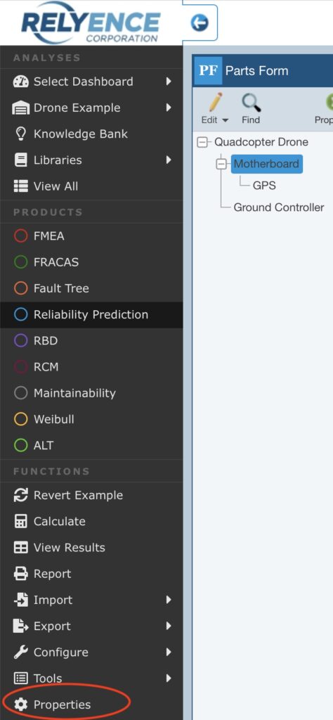
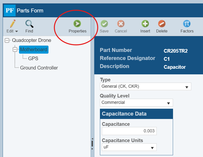
To begin, we first need to enable IEC 61709 calculations in Relyence Reliability Prediction. To do this, click Properties in the Sidebar in Relyence Reliability Prediction:
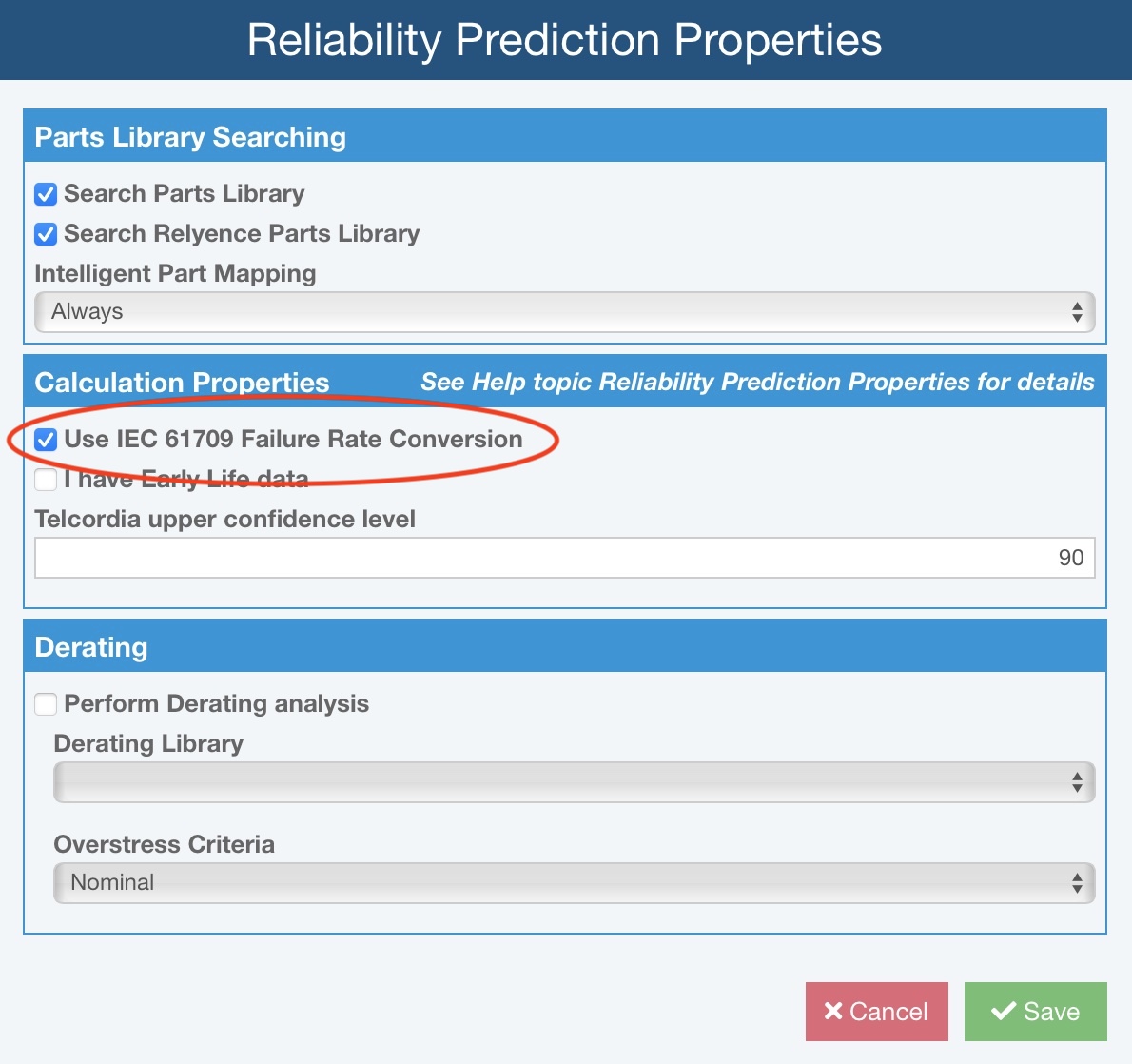
In the Reliability Prediction Properties dialog, select “Use IEC 61709 Failure Rate Conversion.”
Step #1: Determine the Source for Base Failure Rates
For our example, we will evaluate a ceramic capacitor. When using IEC in Relyence, if you have failure rate data from field data or manufacturer data, you simply enter the base failure rate directly into the Parts Table in the Failure Rate, Override field. This article will focus on performing IEC analysis using another Reliability Prediction analysis for base failure rate data since this is an often-used approach. In this example, we will use the failure rate computed using MIL-HDBK-217 reliability prediction standard as our base failure rate. To do so, we select MIL-HDBK-217 FN2 as our Calculation Model.
Here is the predicted failure rate of our capacitor from MIL-HDBK-217:
Step #2: Specify the Environmental Conditions
In Relyence Reliability Prediction, the environmental conditions are specified at the Analysis Tree item level, i.e., at the unit level, not the part level. To access the IEC 61709 environmental factors, select the item in the Analysis Tree pane, then click the Properties icon in the toolbar to view the Analysis Tree item Properties.
On the Analysis Tree item Properties, you will see the IEC 61709 Data section.

The IEC 61709 data include:
- Reference Environmental Application Factor: The environmental application factor for the unit in the environment for which the reference failure rate data is determined. The choices are:
- E1 – Stationary, Weather Protected
- E2 – Stationary, Partial or No Weather Protection
- E3 – Portable, Non Stationary
- Operating Environmental Application Factor: The environmental application factor for the unit in the operating environment, which are the same as the Reference Environment list.
In our example, the reference environment is Airborne, Rotary Winged (ARW), which associates with IEC 61709 E3 – Portable, Non Stationary. This is the same environment our device is operating in. Therefore, we select E3 for both the Reference and Operating Environments.

Step #3: Specify the Operating Parameters for the Parts
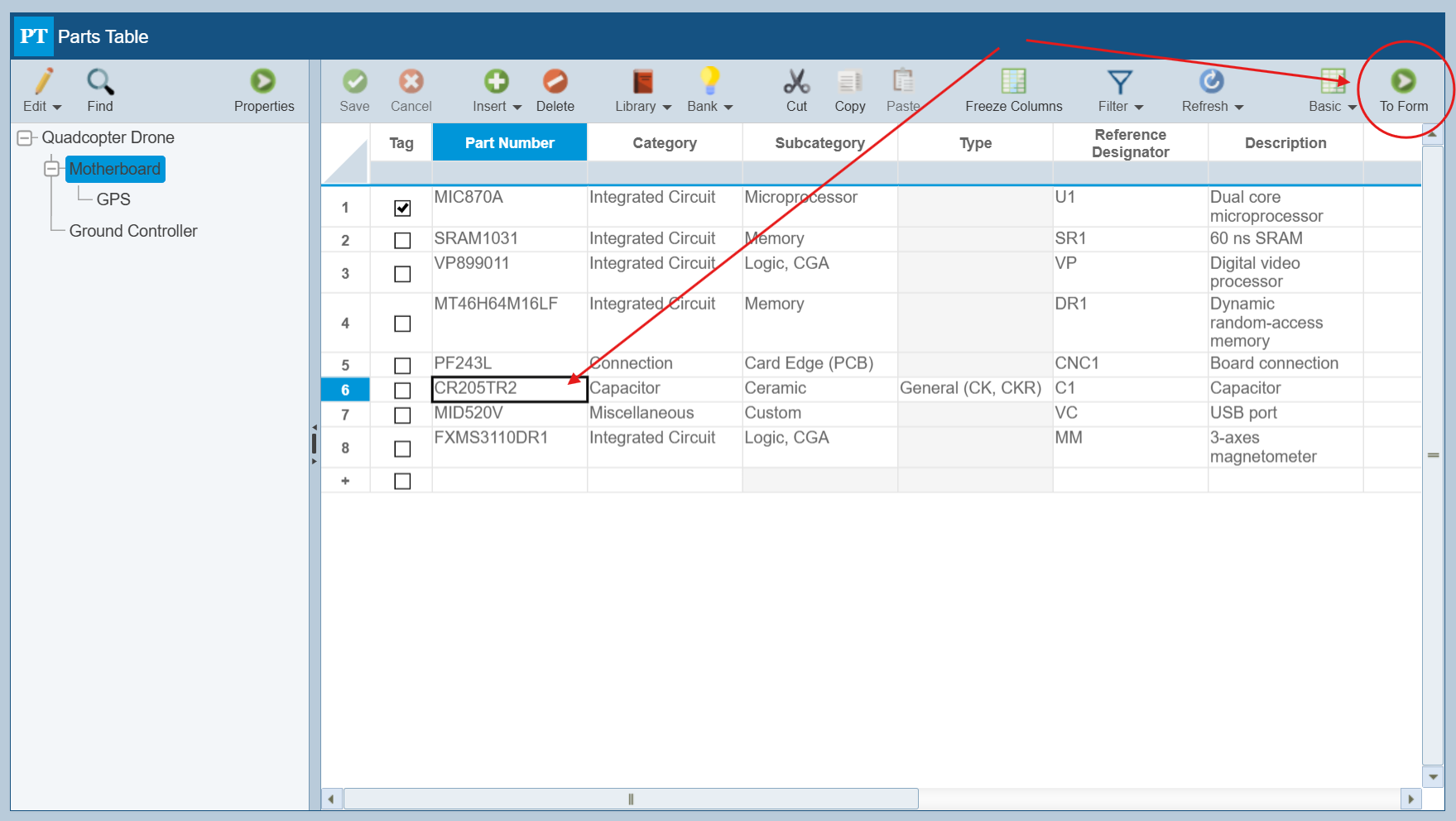
The next step is to enter the operating parameters for the part. To do this, go to the Parts Form by clicking the To Form button on the Parts Table with our ceramic capacitor part selected:
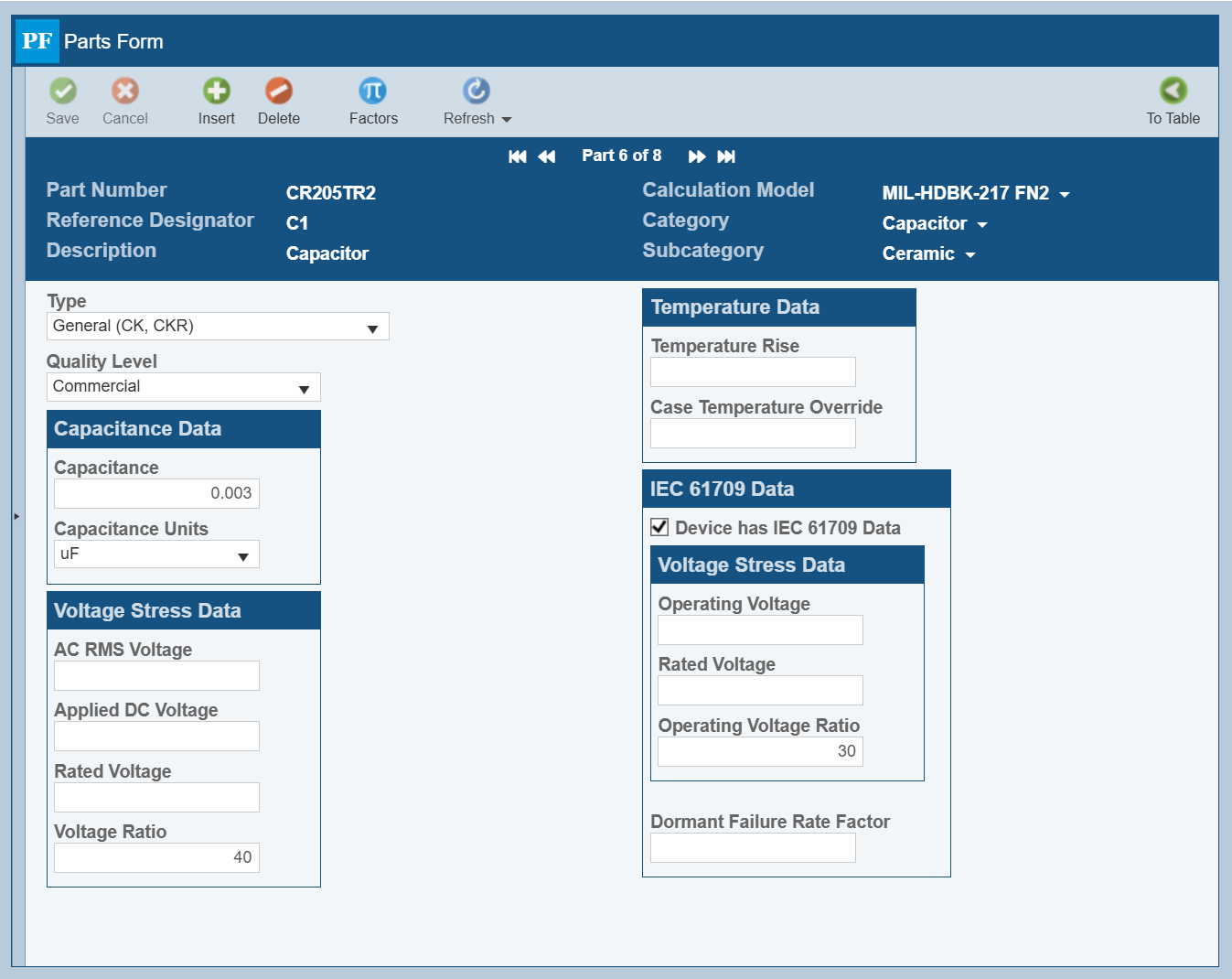
On the Parts Form, we select the “Device has IEC 61709 Data” checkbox to allow us to enter the appropriate operating data for our part. The applicable data parameters needed for conversion will appear. For our example, the reference voltage ratio is 40%, but our actual operating voltage ratio is 30% and our Duty Cycle is 100% so we do not need to set a Dormant Failure Rate Factor.
Step #4: Perform Analysis
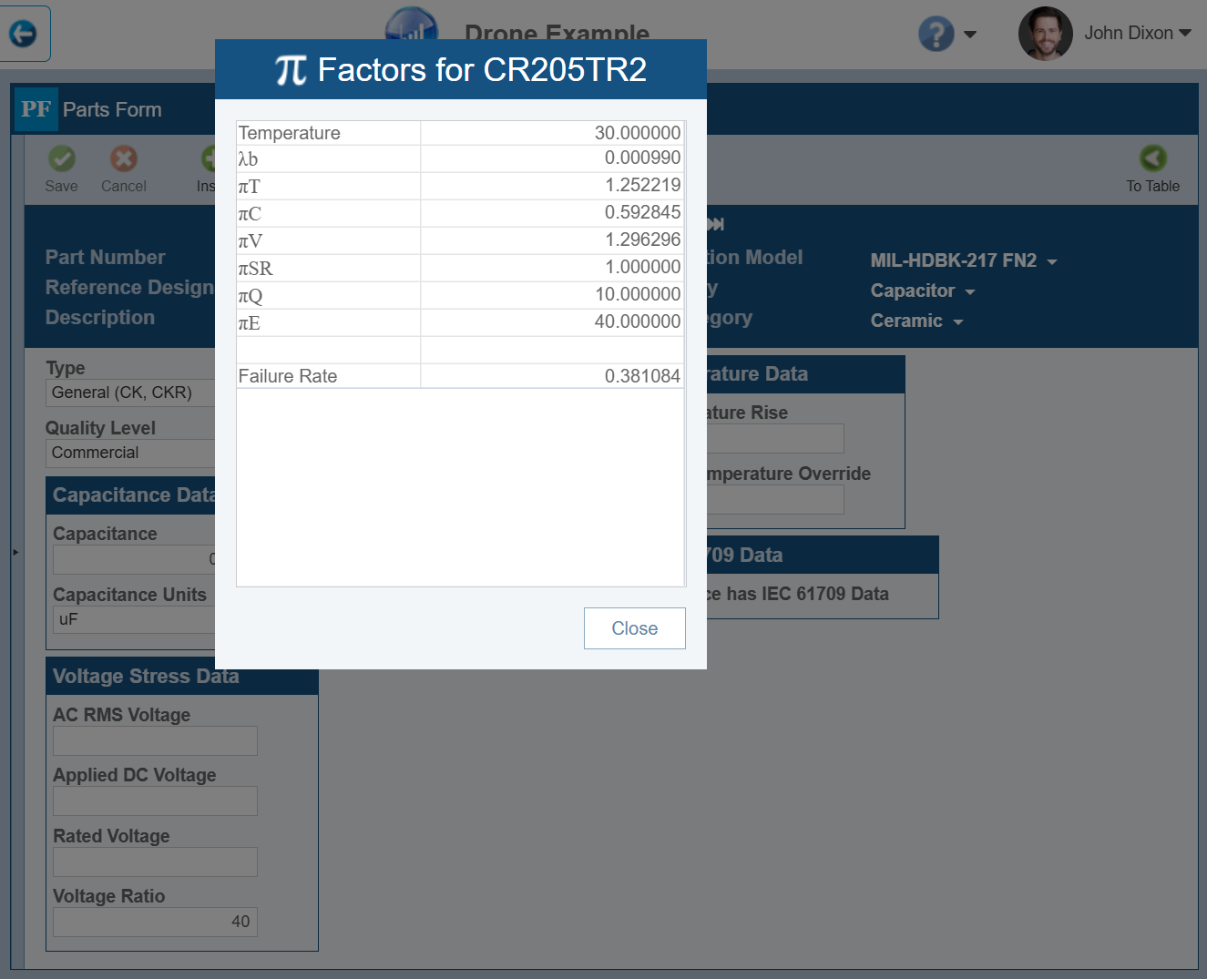
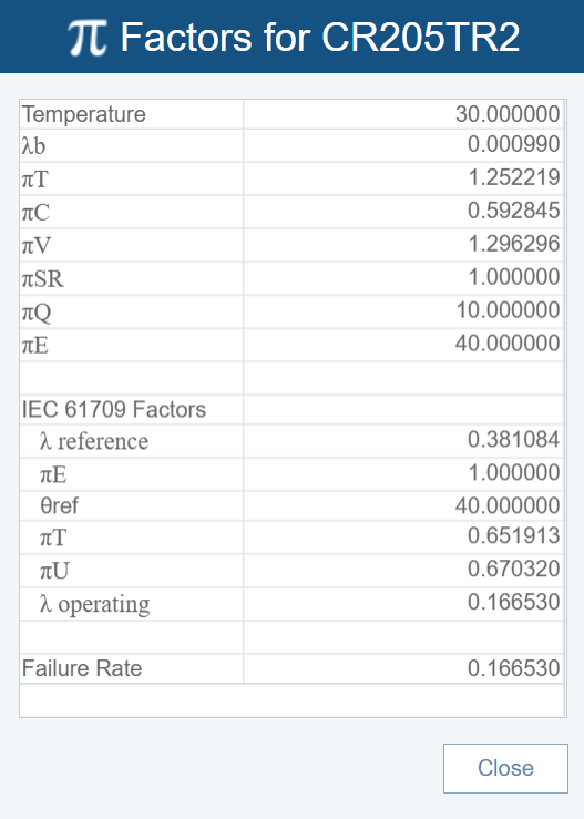
To compute the IEC 61709 failure rate for our part, click the Factors button in the toolbar. When IEC 61709 Data is used, the Factors dialog shows both the factors used to calculate the reference failure rate as well as the IEC 61709 factors.
To calculate the failure rate of the entire system, click Calculate from the Sidebar. You can then view the overall results and generate a report if desired.
Step #5: Evaluate Results
For this example, the operating failure rate is determined by the equation from IEC 61709:
λoperating = λ reference * πE * πT * πU
The reference failure rate, the value determined from using MIL-HDBK-217, is 0.381084 FPMH (Failures per Million Hours). The environmental factor (πE), temperature factor (πT), and stress factor (πU) are determined based on the methodology found in the IEC 61709 standard using the reference and operating conditions for our component. The operating failure rate is computed as:
λoperating = 0.381084* 1.0 * 0.651913* 0.670320 = 0.166530 FPMH
Relyence Reliability Prediction
The best-in-class Relyence Reliability Prediction supports complete and accurate analyses based on all of the widely accepted standards, including IEC 61709. It also offers a host of powerful features to make your reliability prediction tasks quick and efficient. Contact us today so we can talk about your Reliability Prediction needs and how Relyence Reliability Prediction can help your corporation. Sign up for our free trial to see Relyence Reliability Prediction in action, or feel free to schedule a personalized tour with our team.