
Jump to: SAE 1025, FIDES, Maintenance Modeling in RBD
Relyence is excited to introduce Relyence 2026 Release 2, the latest update to our integrated suite of reliability, quality, and risk analysis tools. This release expands standards support with SAE 1025TM in Relyence FMEA and FIDES standard in Relyence Reliability Prediction. It also introduces advanced maintenance modeling in Relyence RBD and delivers a range of enhancements across the Relyence platform.
Major new additions in Relyence 2026 Release 2 include:
- Support for SAE 1025 in Relyence FMEA. Enhance analyses with dedicated Software FMEA and Supportability FMEA analysis types, a preconfigured template, new Worksheet fields, and updates across Design FMEA and Process FMEA.
- Support for FIDES Guide 2022, Edition A in Relyence Reliability Prediction. Apply a detailed, physics-of-failure-based methodology for electronic systems and real-world operating conditions.
- Advanced Maintenance Tasks in Relyence RBD. Model expanded Corrective Maintenance options, Preventive Maintenance, Inspection, Imperfect Repair modeling, and incorporate a reusable Maintenance Task Library.
In addition to these headline capabilities, Relyence 2026 Release 2 includes valuable improvements in FMEA, Fault Tree, Dashboards, the Relyence API, Workflow, Knowledge Banks, and more. Let’s take a closer look at what’s new.
Introducing Support for SAE 1025 in Relyence FMEA
Relyence FMEA is designed to give teams the best of both worlds with built-in support for industry standards and the flexibility to configure terminology, risk criteria, worksheets, and analysis processes around your organization’s needs. With Relyence 2026 Release 2, that standards support expands to include SAE 1025, the new FMEA standard from SAE International covering Design, Supportability, Software, and Process FMEA.
To help teams put the standard into practice, this release introduces a preconfigured SAE 1025 template, dedicated Software and Supportability FMEA types, new Worksheet fields and terminology, and configurable risk criteria and Criticality rules.
What Is SAE 1025?
SAE 1025, titled Failure Mode and Effects Analysis (FMEA) – Includes Criticality Analysis and Design, Supportability, Software, and Process FMEA, establishes a common approach for identifying, evaluating, and reducing risk throughout the product life cycle. The standard includes Criticality Analysis within the broader FMEA methodology, giving teams a consistent way to identify and prioritize the failure risks that require the most attention.
SAE 1025 was developed as a modern replacement for MIL-STD-1629A, which was cancelled in 1998 but remains an important FMEA and FMECA reference in the aerospace and defense industries. The new standard modernizes that foundation while retaining both functional and hardware approaches within Design FMEA. It was also developed to provide a common approach for organizations addressing the DFMEA, PFMEA, Process Flow Diagram, and Control Plan requirements of AS9145.
SAE 1025 covers four primary FMEA types:
- Design FMEA (DFMEA) evaluates potential deficiencies in a product design, from high-level system functions and interfaces to hardware and component-level designs.
- Process FMEA (PFMEA) examines how manufacturing and assembly operations could fail to meet their requirements and connects the resulting risks with Process Flow Diagrams and Control Plans.
- Software FMEA (SwFMEA) focuses on potential deficiencies and failure scenarios associated with software specifications, design, code, data, logic, and interfaces.
- Supportability FMEA (SupFMEA) identifies failures that may occur after a product is placed into service, the maintenance and support resources that may be needed to address them, and opportunities to reduce downtime and support costs through design improvements.
By addressing these four FMEA types within one standard, SAE 1025 provides a shared methodology and terminology that organizations can apply across the product life cycle from design and software development through manufacturing, operation, maintenance, and support.
Start with a Preconfigured SAE 1025 Template
Relyence 2026 Release 2 introduces a new SAE 1025 template and makes it the default when creating a new FMEA Analysis. The template enables Design FMEA, Process FMEA, Software FMEA, and Supportability FMEA, with standard-specific terminology, Risk Criteria, and Worksheet views already configured.
This gives teams a ready-to-use foundation for SAE 1025 analyses while retaining the renowned customization capabilities in Relyence FMEA. Terminology, fields, rating criteria, Worksheets, and other settings can still be tailored to match your organization’s procedures and customer requirements.
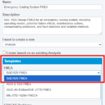
The preconfigured SAE 1025 template provides a ready-to-use starting point for Design, Process, Software, and Supportability FMEA.
New Worksheet Fields and SAE 1025 Terminology
Relyence FMEA now supports key SAE 1025 data elements across the applicable FMEA Worksheets. These new fields keep important operational, maintenance, mitigation, and diagnostic information connected with the failure scenarios it supports.
- Operating Modes. Associates each Function or Process Step with the mission phase or operating state in which it is performed. This helps teams consider how a function or step and its potential failures may behave under different operating conditions. Relyence includes Operating, Non-Operating, and Inactive as default options, and the list can be customized for your products and operating environments.
- Preliminary Maintenance Actions. Records corrective or preventive maintenance recommendations while potential failure Causes are being evaluated. These entries may include servicing, lubrication, calibration, modular replacement, or maintenance of production tooling and equipment. They can then be reviewed and refined by the appropriate supportability or maintenance teams.
- Compensating Provisions. Documents safeguards and responses that can avoid, contain, or reduce the Effect of a failure. Examples may include redundant components, backup operating modes, alarms, safety devices, equipment shutdowns, error-proofing features, or actions performed by an operator. Capturing these provisions makes it easier to understand how the product or process will actually respond to a failure and to reevaluate the resulting End Effects.
- Failure Detection Methods and Fault Isolation Method. Describes how an in-service failure can be recognized and how operators or maintenance personnel can narrow it down to the responsible fault or item. This information may include visual or audible warnings, automatic monitoring, built-in tests, inspections, troubleshooting procedures, and any additional test equipment required.
Operating Modes, Preliminary Maintenance Actions, and Compensating Provisions are configurable, reusable list fields with multi-select pickers, making it easier to standardize commonly used entries across your data. Failure Detection Methods and Fault Isolation Method are flexible text fields, providing room to document the specific indications, procedures, and tools associated with each failure scenario.
The SAE 1025 template also updates familiar FMEA terminology where applicable, including the use of Discovery and Criticality. Configurable Criticality Rules allow users to apply predefined rules to assign High, Medium, or Low levels based on the risk ratings applicable to each FMEA type.
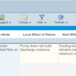
The SAE 1025 DFMEA Worksheet brings standard-specific fields, controls, and risk criteria together in a configurable analysis view.
New Software and Supportability FMEA Types
Relyence 2026 Release 2 adds two dedicated FMEA types: Software FMEA and Supportability FMEA. Both appear in the FMEA Properties dialog and in the Sidebar alongside Design FMEA, Process FMEA, FMEA-MSR, and FMECA.
Software FMEA
Software FMEA introduces four Cause-level ratings designed around the way software failures occur:
- Prevention: considers the independent design controls available to prevent the failure.
- Existence: considers whether a potential deficiency may be present in the software specification, design, code, or interface definition.
- Manifestation: considers whether the conditions needed to trigger that deficiency are likely to occur.
- Detection: considers whether a specific test is in place to find the deficiency before the software is released.
Relyence combines these ratings into a calculated Likelihood of Occurrence value and evaluates it with Severity in a configurable two-axis Criticality matrix. This gives software teams a risk-assessment approach centered on software Causes, design safeguards, and test coverage instead of requiring software risks to fit a traditional hardware failure model.
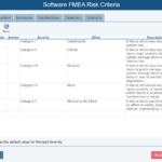
Configurable Software FMEA Risk Criteria support software-specific Cause ratings and Criticality evaluation.
Supportability FMEA
Supportability FMEA extends the analysis beyond design and manufacturing to consider what happens after a system is placed into service. Teams can identify potential in-service failures, determine the maintenance and support resources that may be needed to correct or mitigate them, and uncover design improvements that could reduce maintenance demands, downtime, and long-term support costs.
Beginning this analysis early also helps teams compare potential support concepts and design-versus-supportability tradeoffs before the design is finalized. The analysis can then be updated as operating and maintenance experience is gained, providing a stronger foundation for downstream maintenance and support planning.
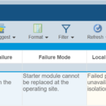
Supportability FMEA captures in-service failure effects, maintenance needs, and restoration challenges.
Dedicated Dashboard widgets are also available for Software FMEA and Supportability FMEA, giving teams visual tools for reviewing trends, communicating results, and focusing attention on the most important risks from each analysis type.
More Enhancements in Relyence FMEA
Beyond the new SAE 1025 capabilities, Relyence 2026 Release 2 includes additional FMEA enhancements that strengthen connections across your analyses and make it easier to carry important information forward. New Control Plan and SmartSuggestTM capabilities help teams reuse established PFMEA data, reduce duplicate entry, and keep information aligned throughout the FMEA process.
Bring More PFMEA Context into Your Control Plans
Relyence FMEA’s always-in-sync capability already keeps Process Steps, Characteristics, and Controls aligned across your Process Flow Diagrams, PFMEA Worksheets, and Control Plans. With Relyence 2026 Release 2, you can bring even more of your PFMEA information directly into the Control Plan.
Failure Mode, Cause, Effect, and Recommended Action fields can now be added to the Control Plan, allowing teams to create more complete and informative documents. This makes it easier for anyone reviewing the control plan to understand not only what must be controlled, but also the failure risks and recommended actions associated with each control. This expanded flexibility can also support Dynamic Control Plan formats, which combine PFMEA and Control Plan information within a single document.
Control Methods can now also include attachments and images, making it easier to provide supporting documents or visual guidance alongside the plan.
Because Relyence FMEA Worksheets and Control Plans are fully customizable, you can include the additional information that is valuable to your organization on one worksheet View while retaining a streamlined Control Plan View when less detail is needed.
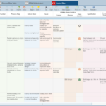
Control Plan Worksheets can now include failure information such as Failure Mode, Cause, Effect, and Action fields, allowing teams to create more complete and informative documents.
Connect Controls and Characteristics with SmartSuggest
New SmartSuggest capabilities make it easier to carry established PFMEA information forward in your Analyses.
Prevention and Detection or Discovery Controls from the PFMEA Worksheet can now be used to populate Process Controls on the Control Plan. SmartSuggest can display all available Controls, Controls associated with the current Process Step, or associated Controls that have not yet been used. This reduces duplicate data entry and helps teams maintain stronger connections between their PFMEA Worksheets and Control Plans.
SmartSuggest can also assign Product and Process Characteristics directly on DFMEA and PFMEA Worksheets. Where applicable, PFMEA suggestions reflect the Characteristics already associated with the current Process Step through the Process Flow Table. This makes it easier to reuse existing Characteristic definitions and maintain alignment as information moves through the FMEA process.
New Support for FIDES in Relyence Reliability Prediction
Relyence Reliability Prediction enables fast, standards-based failure rate analysis using prediction methodologies, including MIL-HDBK-217, Telcordia, 217Plus, NSWC-11, SN 29500, and more. Relyence 2026 Release 2 expands that list with FIDES Guide 2022, Edition A, providing a detailed physics-of-failure-based approach for evaluating electronic systems across real-world operating conditions.
What Is FIDES?
The FIDES Guide is a reliability methodology for electronic systems. It was developed by a consortium from the aerospace and defense sectors under the direction of France’s defense procurement agency, the Direction Générale de l’Armement (DGA), and is made available through the Institut pour la Maîtrise des Risques (IMdR). FIDES Guide 2022, Edition A was published in July 2023 and replaced FIDES Guide 2009, Issue A.
FIDES combines a failure rate prediction guide with a reliability process control and audit guide. Its prediction methodology uses a physics-of-failure foundation informed by test data, operating experience, and existing reliability models, accounting for both the physical factors that influence component reliability and the life-cycle processes that can activate, accelerate, mitigate, or prevent failures.
What Makes the FIDES Approach Different?
FIDES brings physical models, mission-specific operating conditions, and life-cycle process factors together in a single methodology. It also provides broad coverage for electronic components and subassemblies, helping teams build predictions that more closely reflect the product, its environment, and the processes used throughout its life cycle.
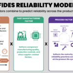
- Physical and technological contribution. FIDES is built on a physics-of-failure foundation, accounting for identified failure mechanisms and the physical and technological factors that influence component reliability. Detailed mission profiles represent the different phases and conditions a product experiences throughout its life, accounting for factors such as phase duration, temperature, thermal cycling, humidity, vibration, pollution, electrical loading, and accidental overstress.
- Part manufacturing factor. FIDES accounts for the quality and reliability of component manufacturing, including information about the component manufacturer, production controls, qualification practices, and supplier-related factors. This helps distinguish between otherwise similar components whose manufacturing quality or supplier practices may result in different reliability performance.
- Process factor. FIDES evaluates the maturity and effectiveness of reliability practices applied throughout the product life cycle. This includes activities associated with specification, design, board manufacturing, equipment and system integration, operation, and maintenance, allowing the prediction to reflect how well reliability is managed beyond the component itself.
FIDES provides models for a broad range of electrical, electronic, and electromechanical components, including printed circuit boards, RF and microwave components, COTS boards, and selected subassemblies. At a high level, the FIDES model can be summarized as:
Predicted failure rate = Physical and technological contribution × Part manufacturing factor × Process factor
A Component-Level Example: The Resistor Model
To see how the high-level model translates into a calculation, consider the FIDES resistor model, one of the simpler component families in the guide:

Where:
- πPM – the part manufacturing factor
- πProcess – the process factor
And:

Where:
- λ0_Resistor – the base failure rate for the resistor type
- tphase/Ttotal – the proportion of the year spent in a given mission phase
- πThermo-electrical; πTCy; πMechanical; πRH – stress contributions from thermo-electrical loading, thermal cycling, mechanical stress, and humidity
- πinduced – an overstress contribution reflecting placement, application, ruggedization, and technology sensitivity
Two characteristics distinguish this from the calculation models already available in Relyence Reliability Prediction. First, the stress terms inside the bracket are added rather than multiplied, so a component’s exposure to loading, cycling, stress, and humidity are each accounted for independently rather than compounded into a single chain of pi factors. Second, accounts for any overstress condition and the tphase / Ttotal term calculates the physical contribution separately for each mission phase before the results are combined. The πPM and πProcess terms then apply on top, incorporating the manufacturing quality and process-control contributions.
A Mission-Profile-Based Example
Mission Profiles are an important part of the FIDES methodology because electronic systems rarely operate under a single set of conditions throughout their lives. Instead, FIDES allows different operating phases to be modeled independently, with each phase reflecting the environmental and operational stresses the product experiences during that portion of its mission.
Consider a flight controller board in a commercial drone. Over the course of a typical year, the controller spends most of its time powered off, a small amount of time operating in flight, and an even smaller amount of time powered on during pre-flight preparation. A simplified Mission Profile might look like this:
| Phase | Calendar Time (h) | State | Ambient Temperature | Vibration |
| Off | 8,535 | Off | 20°C | 0.01 grms |
| Ground-On | 45 | On | 35°C | 2.0 grms |
| Flight | 180 | On | 28°C | 6.0 grms |
Each phase can include its own temperature, thermal cycling, humidity, vibration, electrical loading, pollution, and other applicable conditions. FIDES calculates the physical contribution to the failure rate for each phase and weights it according to the amount of time the product spends in that environment.
In this example, the flight phase represents only a small portion of the year but subjects the controller to substantially greater vibration and operating stress. The powered-off phase accounts for most of the calendar time but contributes comparatively little operating stress. Modeling these conditions separately allows the prediction to more closely reflect how the product is actually used rather than assuming one continuous operating environment.
Using FIDES in Relyence Reliability Prediction
FIDES is available as an optional licensed calculation model. To begin a FIDES analysis in Relyence, select FIDES 2022 from the Calculation Model dropdown on the Analysis Tree or Parts Table, just as you would select another supported prediction methodology.
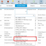
FIDES can be used alongside other supported calculation models within the same Analysis. For example, a team could use FIDES for the electronic components in a system while using NSWC Mechanical for its mechanical components, without creating separate system structures. This flexibility allows reliability teams to select the most appropriate methodology for each part of a product, customer program, or system analysis.
Advanced Maintenance Task Modeling in Relyence RBD
Relyence RBD combines an intuitive visual diagrammer with an advanced calculation engine to evaluate system reliability, availability, redundancy, and downtime using analytical methods and Monte Carlo simulation.
When analyzing a system, maintenance strategy can have just as much impact on availability as the underlying failure behavior. A component may be repaired immediately after failure, left in a failed state until an inspection discovers it, serviced on a fixed schedule, or maintained only after a defined condition is reached. Accurately representing these differences is essential for understanding how a system will perform in operation.
Relyence 2026 Release 2 significantly expands the maintenance options available for RBD blocks. Relyence now supports three maintenance task categories of Corrective Maintenance, Preventive Maintenance, and Inspection, along with new Imperfect Repair options that provide greater control over how blocks are restored. The built-in Maintenance Task Library lets you define tasks once and reuse them consistently across RBD models, reducing repetitive setup and helping maintain accurate maintenance assumptions.
Corrective Maintenance
Corrective Maintenance defines how a block is restored after it fails. In addition to defining the Repair distribution and parameters, you can now specify the event that initiates corrective action:
- Immediate: Repair begins as soon as the block fails.
- Upon Inspection: Repair begins only after a scheduled Inspection discovers the failed block, supporting hidden-failure scenarios.
- Upon System Failure: Repair begins when the overall system fails, even if the individual block failed earlier.
- Upon System Failure or Inspection: Repair begins when either event occurs first.
These options allow the simulation to represent the time between failure and the start of repair, not just the repair duration itself.
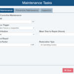
The Corrective Maintenance tab includes Library Maintenance Task selection, trigger behavior, repair distribution, Mean Time to Repair, and Imperfect Repair options.
Preventive Maintenance
Preventive Maintenance represents planned work performed before failure to help keep equipment operating and reduce the likelihood or impact of an unplanned outage. In Relyence RBD, Preventive Maintenance can be configured in two ways:
- Interval: Performs maintenance at a defined Maintenance Interval. The interval can be based on Calendar Time, which follows elapsed simulation time, or Item Age, which follows the block’s accumulated effective age.
- On Condition: Performs maintenance when a modeled condition reaches a defined threshold. On Condition tasks use a Condition Type and Condition Threshold, such as Life Proportion, along with a Maintenance Trigger.
Preventive Maintenance tasks also define a Repair distribution and parameters and specify whether the block is unavailable while maintenance is performed.
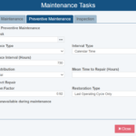
Preventive Maintenance settings support scheduled service, repair timing, downtime, and partial restoration.
Inspection
Inspection tasks represent scheduled checks used to reveal failures that are not immediately apparent. You can define the Inspection Interval and Inspection Duration and specify whether the block is unavailable while the inspection is being performed.
Inspection is especially useful when combined with Corrective Maintenance configured for Upon Inspection or Upon System Failure or Inspection. For example, a redundant component may fail without immediately causing a system outage. The component can remain in a hidden failed state until the next inspection discovers it or until the broader system fails and initiates corrective action.
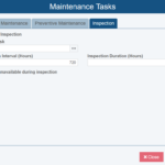
Inspection task settings include interval, duration and specify whether the block is unavailable during inspection.
This allows the simulation to distinguish between when a failure occurs, when it is discovered, and when the resulting repair begins, providing a more realistic representation of hidden-failure scenarios.
Imperfect Repair
Maintenance does not always return equipment to as-good-as-new condition. Imperfect Repair allows you to represent maintenance that corrects a failure or improves a block’s condition while leaving some accumulated age or damage in place.
Imperfect Repair is available in the block’s Repair Parameters and can also be applied to Corrective and Preventive Maintenance tasks, allowing partial restoration to be represented within either the block’s general repair behavior or a specific maintenance strategy.
Two settings define the restoration behavior:
- Restoration Factor: A value from 0 to 1 that indicates how much of the block’s applicable accumulated damage is removed by the maintenance action. A value of 1 represents a perfect repair and resets the block’s effective age to zero, while a value of 0 removes no accumulated damage. Values between 0 and 1 partially reduce effective age; for example, a Restoration Factor of 0.8 removes 80% of the applicable accumulated damage and leaves 20% in place.
- Restoration Type: Determines which accumulated damage is reduced. All Operating Cycles applies the Restoration Factor to the block’s total effective age, while Last Operating Cycle Only applies it only to the age accumulated since the previous maintenance action.
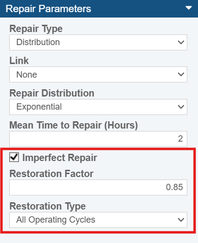
Imperfect Repair settings define how much accumulated age is removed during maintenance and whether restoration applies to all operating cycles or only the most recent cycle.
For example, assume a block has an effective age of 1,000 hours when maintenance occurs. With a Restoration Factor of 0.8 applied to All Operating Cycles, the maintenance removes 800 hours of accumulated effective age and the block resumes operation at an effective age of 200 hours. Its future failure behavior is then based on the failure distribution at 200 hours—not on a new component starting at zero or on a component operating at “80% reliability.”
Imperfect Repair is most meaningful for age-dependent failure distributions, where failure behavior changes as a block accumulates operating age. Because an exponential distribution has a constant failure rate, changing the effective age of a block that uses an exponential model does not change its subsequent failure behavior.
Reusable Maintenance Task Library
Maintenance tasks and schedules are often shared across multiple blocks or reused in several RBD models. Defining these tasks in a Library reduces repetitive setup, helps standardize task durations and other maintenance parameters, and makes it easier to keep common strategies consistent as an analysis evolves.
To add a Maintenance Task to the Library, select Libraries > Maintenance Tasks from the Relyence RBD sidebar, then define the Task type and its associated parameters.
Once defined, the task can be assigned from the Library Maintenance Task field on the corresponding tab of the Maintenance Tasks dialog. Updates to the Library task are reflected wherever it is used, saving time and helping maintain consistent assumptions throughout the model.
The RBD Maintenance Tasks Library lets teams define reusable maintenance activities and apply consistent task parameters across blocks and Analyses.
Together, the new Maintenance Tasks dialog and expanded Imperfect Repair support make it possible to model immediate and delayed corrective action, fixed-schedule and condition-based preventive maintenance, hidden failures, inspection downtime, and partial restoration. These capabilities provide a more complete view of how maintenance timing, task duration, and restoration effectiveness influence system availability and downtime. It also makes it easier to compare practical maintenance strategies before they are implemented.
For a detailed example, see How to Model Maintenance Activities in Relyence RBD, which compares a reactive maintenance baseline with strategies that add scheduled Inspection and Preventive Maintenance to a remote-facility security system.
Additional Enhancements in Relyence 2026 Release 2
Beyond the major additions above, Relyence 2026 Release 2 includes additional improvements that simplify data exchange, help teams navigate complex analyses, and provide greater access to important results.
- Improved FMEA imports and exports: DFMEA imports can automatically connect Failure Modes to matching Higher Level Causes. DFMEA and PFMEA imports and exports also preserve the Occurrence and Detection or Discovery ratings associated with Controls, helping maintain complete risk information when exchanging data with Excel or connected systems.
- More focused Repeat Event searches: When inserting a Repeat Event in Relyence Fault Tree, you can choose to search the Current Fault Tree only, the Current Fault Tree and Subtrees under transfer gates, or all Fault Trees in the file. This makes it easier to locate the correct event in large or complex analyses.
- AP Level filtering for Recommended Actions: The Recommended Action Status widget on DFMEA, PFMEA, and FMEA-MSR Dashboards can now be filtered by AP Level, helping teams focus on the actions requiring the most attention.
- Maintainability results through the Relyence API: Maintainability Prediction results can now be retrieved programmatically through the Relyence API, expanding the analysis data available for integrations, reporting, and custom applications.
- Workflow configuration improvements: Team Member Data Fields are now grouped by type when configuring notification recipients, making the appropriate field easier to locate.
- Clearer Knowledge Bank progress: Operations for adding and untying Knowledge Bank data now display progress as they run, providing clearer feedback when working with large Analysis Trees.
Experience Relyence 2026 Release 2
We’re proud to deliver Relyence 2026 Release 2, with new capabilities that help reliability and quality teams meet evolving program requirements, model real-world behavior more accurately, and work more efficiently across the Relyence platform.
Relyence Cloud-Hosted customers can begin using these new capabilities immediately. Relyence On-Premise customers will receive the update through their normal upgrade process.
We sincerely thank our customers for their continued feedback and support. Your input plays an important role in shaping our ongoing improvements and future releases.
Not yet a Relyence customer? Start a free trial today or contact us to schedule a demo and explore everything Relyence 2026 Release 2 has to offer.